
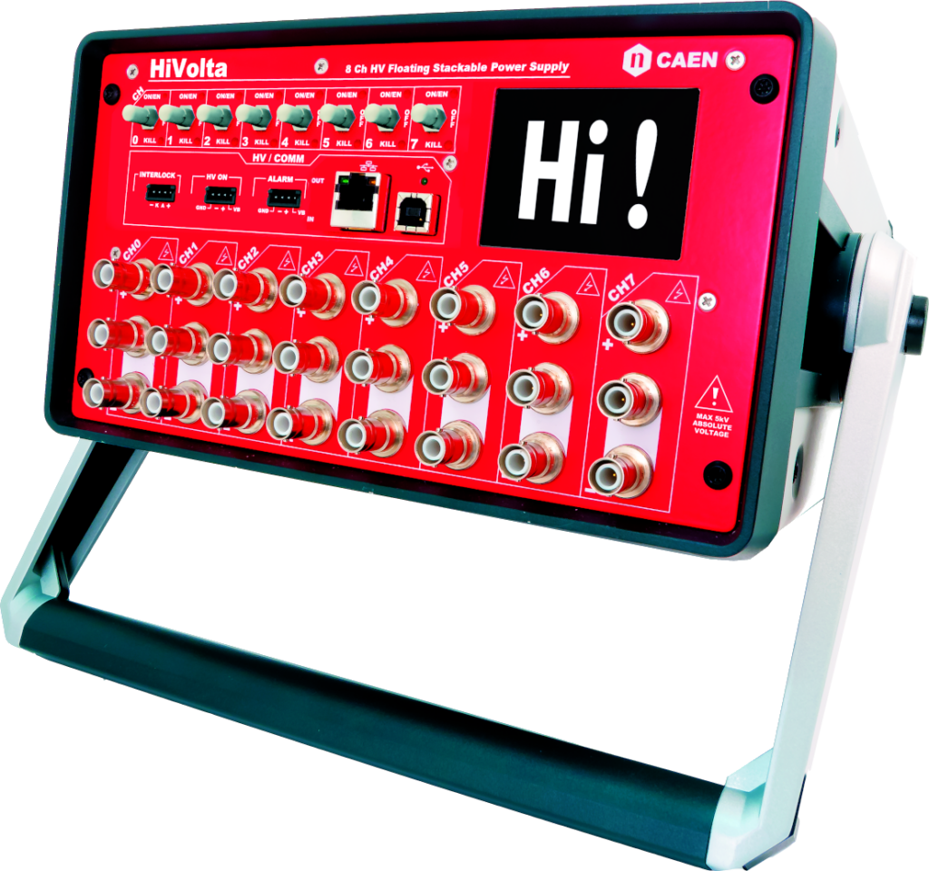
HIVOLTA (DT1415ET)
8 Ch Reversible 1 kV/1 mA Desktop HV Power Supply High Accuracy Module (USB/Ethernet/T.screen)
Highlights
-
8 independent channels in a Desktop package (110/220V AC Powered)
-
1 kV / 1 mA (0.6W) output range
-
Floating Channels
-
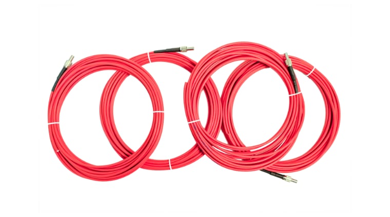
SHV coaxial output connectors
-
Floating return up to 5kV
-
Stacking channels capability: up to 5kV output
-
Low Ripple
-
Under/Over Voltage alert, overcurrent and max. voltage protection
-
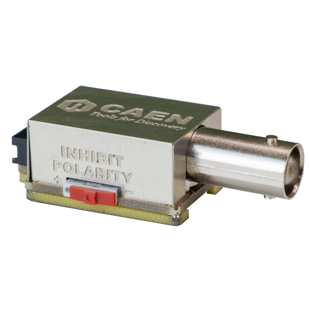
Interlock logic for board enable and Individual channel kill
-
1 nA Current monitor resolution (with x10 Imon-Zoom: 100 pA)
-
2.8″ color touch screen display
-
Local and Remote control (USB2.0/Ethernet)
-
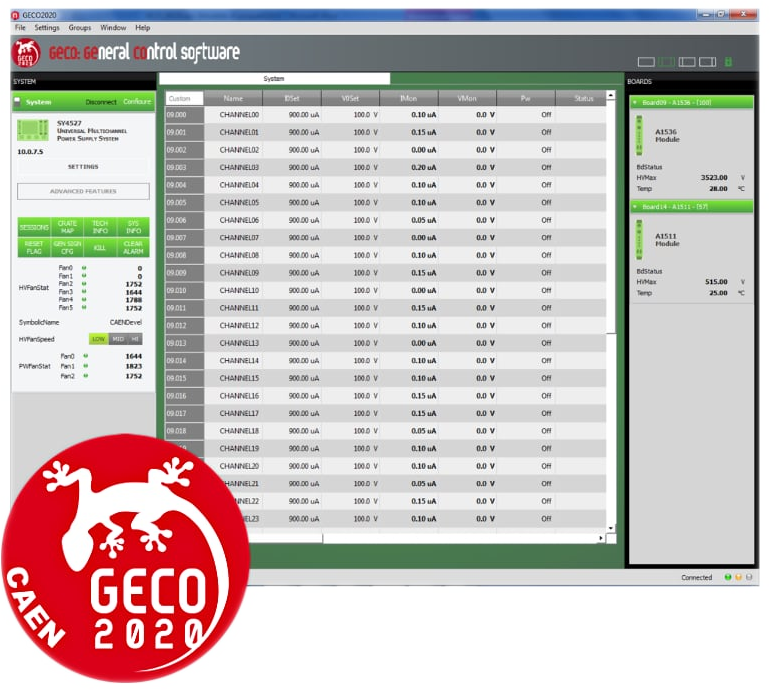
Software Tools for easy channel management
Overview
The CAEN Mod. DT1415ET (HiVolta) provides 8 independent High Voltage 1 kV / 1mA (0.6W) channels in a desktop package; the unit is 110/220V AC Powered.
Channels can be used with either positive or negative polarity, independently from each other. The channels have independent floating return, insulated up to 5 kV one from another (Full Floating channel). Each channel is provided with one connector for the positive output and two “bridged” for the negative one, thus allowing to “stack” two or more adjacent channels. Module control can take place either locally, assisted by a 2.8″ Touchscreen Graphic colour LCD display or remotely, via USB, or Ethernet. HV outputs are delivered through SHV connectors.
|
SHV connector Radiall R317580 HV coaxial connector for Mod.DT1415ET |
Consult our connectors reference page for technical information.
A complete set of Software Tools is available to control these units; the user can freely download low level libraries, LabVIEW driver and Graphical application software.
Safety features allows the module to perform as a current generator and includes:
|
Overvoltage and Undervoltage warning |
when the output voltage differs from the programmed value by more than ±1% ±2V of set value. |
|
Overcurrent detection |
when a channel attempts to exceed the programmed current limit (Iset), it signaled to be in “overcurrent” and enter in a TRIP status. The output current is varied to keep the current below the programmed limit for a programmable TRIP time, then the channel is switched off. If TRIP is set to “constant current mode”, the channel behaves like a current generator. |
|
Hardware VMAX |
maximum output voltage can be set, via front panel potentiometer, at the same common value for all the board channels. VMAX value can be read out via software. |
|
Safety Board Interlock |
Common Interlock logic for channels enable/disable and individual inputs signal for channel Kill function. |


Request a Quote

Technical Specifications

|
Packaging |
Desktop package (255 x 140 x 330 mm); Weight: ~5.2 kg |
|
No. of Channels |
8 |
|
Output Voltage |
1 kV |
|
Polarity |
Floating 5 kV Max. |
|
Output Current |
1 mA Max. |
|
Channel Power |
0.6W |
|
Voltage Set/Monitor Resolution |
20 mV |
|
Current Set Resolution |
20 nA |
|
Current Monitor Resolution |
High Power: 1 nA |
|
Ramp Up/Down |
1÷100 Volt/sec, 1 Volt/sec step, settable for each channel |
|
Trip |
Max. time an “overcurrent” is allowed to last (seconds). A channel in “overcurrent” works as a current generator; output voltage varies to keep the output current lower than the programmed value. “Overcurrent” lasting more than set value, causes the channel to “trip”. Output voltage will drop to zero at the Ramp-down rate; in this case the channel is put in the off state. If trip= INFINITE, “overcurrent” lasts indefinitely. TRIP range: 0 ÷ 999.9 s; 1000 s = Infinite. Step = 0.1 s |
|
“Zero” current |
Zero Current Detect channel parameter allows to sample the present IMon value; this value (IMonZero) can be then subtracted via the Zero Current Adjust parameter ENABLE, from the monitored current (IMon), to compensate the current offset; if ZCAdjust = Enabled, then the IMon value is compensated. After the IMonZero value is sampled, Zero Current Detect, returns to Off. Allowed IMonZero values are from 0 to full scale. If Zero Current Adjust is DISABLED, the IMonZero compensation is neglected. |
|
Voltage Ripple |
Differential mode:
Common Mode:
|
|
Voltage Monitor vs. Output Voltage Accuracy |
±0.2% of VSet ± 0.2V from 10% to 100% f.s. |
|
Voltage Set vs. Output Voltage Accuracy |
±0.2% of VSet ± 0.2V from 10% to 100% f.s. |
|
Iset vs Output current accuracy |
±0.5% of ISet ± 0.5µA from 3% to 100% f.s. |
|
Imon vs Output current accuracy |
±0.5% ±5 nA ±50 ppm/°C with output current from 10% to 100% f.s. and constant voltage |
|
Power requirements |
100-240 Vac; 50/60 Hz; 0.8A rms max; fuse: 2xT1A 6.3×32 250 Vac |
|
Humidity range |
0 ÷ 80% non condensing |
|
Operating temperature |
0 ÷ 45°C |
|
Storage temperature |
-10 ÷ 70°C |
|
MTBF |
28000 hours |
|
Temperature coefficient |
±50 ppm/°C |
|
Stability |
< 150 mV (Vset = 750V; No Load; one day after 1 hour warm up) |
|
Long term stability |
< 200 mV (Vset = 750V; No Load; one week after 1 hour warm up) |
|
Load regulation |
< 0.2% (Vset = 600V, Iout from 60 µA to 850 µA) |
|
EMC qualification |
CE Standards |
|
Safety Standard |
ROHS |
Footer