
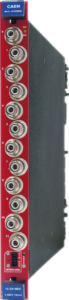
A1515B
16/14 Channel 1-1.4kV (1 - 3 mA) Full Floating Channel Dual Range Boards for Quadruple and Triple GEM detectors
Highlights
-
16 independently controllable High Voltage channels
-
1 kV/1.3 kV/1.4 kV maximum output voltage
-
Dual range current:
-
High Power: 1 mA or 3 mA (1 nA or 4 nA Current monitor resolution)
-
High resolution: 1 mA or 3 mA (1 nA or 4 nA Current monitor resolution)
-
-
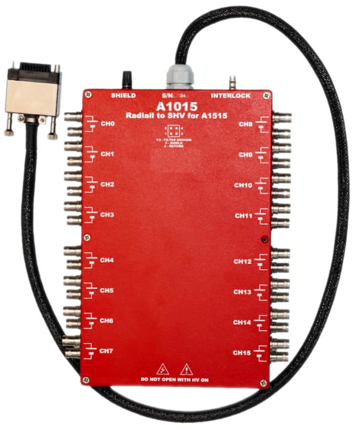
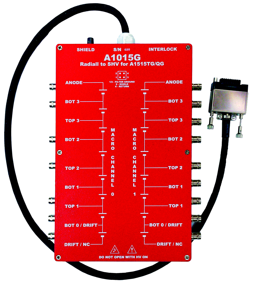
Radiall 52 pin or Redel 51 pin connectors (see Ordering Options)
-
Floating Type: Full Floating (insulated up to 5 kV)
-
Zero current function
-
Under/over-voltage alert, overcurrent and max. voltage protection
-
Interlock logic for unit enable
-
Software Tools for easy channel management
Overview
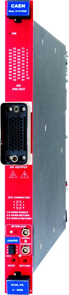
The A1515B family are single width boards (5 TE wide) that house 14 or 16 (see Ordering Options) independent, Full Floating high voltage individual channels. Which are perfectly suited for GEM detectors.
The A1515B is supplied in different versions equipped with Radiall or REDEL multipin connector.
Consult our connectors reference page for technical information. As an option, it is possible to request that the REDEL connector be mounted on any version of the A1515B. The following table shows the available models:
|
|
Model |
Max V |
Max I |
# of ch |
Features |
|
|
A1515BTG |
1 kV |
1/0.1 mA |
14 |
For Triple GEM chambers |
|
|
A1515BQG |
1 kV |
1/0.1 mA |
16 |
For Quadruple GEM chambers |
|
|
A1515BQGA |
1 kV |
1/0.02 mA |
16 |
For Quadruple GEM chambers |
|
|
A1515BCG |
1.3 /1 kV |
1/0.1 mA |
14 |
For Triple Cylindrical GEM chambers |
|
|
A1515BTGHP |
1/0.6 kV |
3/0.3 – 1/0.1 mA |
14 |
For Triple GEM chambers (high rate) |
|
|
A1515BV |
1.4 kV |
1/0.1 mA |
16 |
For Vertex detector |
|
|
A1515B |
1 kV |
1/0.1 mA |
16 |
Non Stacked channels |
The channels have floating return, independent one from another, insulated up to 5 kV (Full Floating channel). The output voltage range is 0 ÷ 1 kV or 0 ÷ 1.3 kV with 20 mV set and monitor resolution.
The output channels offer dual current ranges (software selectable):
|
|
For A1515BTG/A1515BQG |
|
|
|
|
High Power: 0 ÷ 1 mA |
|
High Resolution: 0 ÷ 100 µA |
|
|
I set resolution: 20 nA |
|
I set resolution: 20 nA |
|
|
I mon resolution: 1 nA |
|
I mon resolution: 100 pA |
|
|
For A1515BTGHP: |
|
|
|
|
High Power: 0 ÷ 3 mA |
|
High Resolution: 0 ÷ 300 µA |
|
|
I set resolution: 50 nA |
|
I set resolution: 50 nA |
|
|
I mon resolution: 4 nA |
|
I mon resolution: 400 pA |
|
|
For A1515BV/A1515BVR: |
|
|
|
|
High Power: 0 ÷ 1 mA |
|
High Resolution: 0 ÷ 100 µA |
|
|
I set resolution: 20 nA |
|
I set resolution: 20 nA |
|
|
I mon resolution: 1 nA |
|
I mon resolution: 100 pA |
Independently programmable for each channel:
|
|
Output voltage: |
|
0 ÷ 1/1.4 kV |
|
step: 50 mV |
|
|
Current limit (Iset): |
|
0 ÷ 1 mA/100 µA 0 ÷ 3 mA/300 µA |
|
step: 20 nA step: 50 nA |
|
|
V Ramp up/down: |
|
1 ÷ 100 V/s |
|
Step: 1 V/sec |
|
|
TRIP parameter |
|
0 ÷ 999.9 s; 1000 s = Infinite |
|
Step: 0.1 s |
Five special version of the board (A1515BVTG/QG/CG/TGHP/V/VR) have been designed specifically for Gas Electron Multiplier (GEM) detectors (Triple, Triple designed for high rate, Quadruple, Cylindrical GEM detectors and Vertex detectors). These boards have the channels internally stacked in order to power up 2 independent Triple GEM / Quadruple GEM / Triple Cylindrical GEM chambers. This configuration permits to avoid any possible issue related to the detector discharge and avalanche effects and gives the possibility to fine tune the voltage on each detector layer easily.
A CAEN SY4527 mainframe equipped with 16 boards can power 32 detectors and the high maximum current available on each channel allows managing the high segmentation of these detectors in the best way. The high max current per channel feature designed into these boards is beneficial for managing the high segmentation of GEM detectors, as it will allow discrete detector layers to perform even in the event of a short. In addition, the 2-quadrant 100 µA low current range allows a 100 pA current monitoring resolution which allows the monitoring of ion backflow currents and also to perform real-time detector diagnostics.
In the GEM dedicated version of the A1515B in the overcurrent condition causes the following actions:
· A1515B or A1515TG/QG/CG/TGHP/V/VR (not in GEM-mode): the channel is switched off. Output voltage will drop to zero at Ramp-down rate. If TRIP is set to “constant current mode”, the channel behaves like a current generator.
· A1515BTG/QG/CG/TGHP/V/VR (in GEM-mode): all stacked channels are switched off, following a programmed sequence. Output voltages will drop to zero at Ramp-down rates. If TRIP is set to “constant current mode”, the channel behaves like a current generator. The channels can be enabled or disabled through the Interlock logic. The voltage ramp rates may be set independently for each channel.
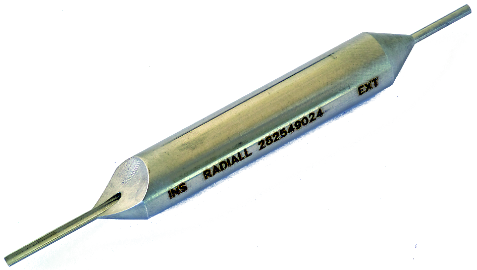
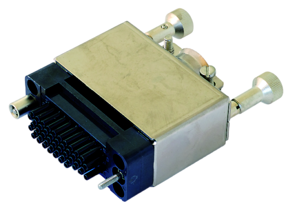
Moreover, for board equipped with Radiall 52 pin connector the following accessories are available: Mate cable connector (Mod. A996) and relevant insertion/extraction tool (Mod. A995).
CAEN provides a complete software range to control, monitor and configure its Power Supply products.
-
GECO2020 GEneral COntrol Software
-
CAEN HV Wrapper Library,
-
HiVoCS web tool
-
OPC Server for CAEN Power Supplies
-
EPICS Service
These tools, which support the most used operating systems, spread from low level libraries (CAEN HV Wrapper Library), to be used as a source for customer designed software, to the WEB interface (HIVOCS) available on each mainframe, up to the all-inclusive Control Software (GECO2020) with user friendly graphical interfaces, to meet any application need.
Advanced control via OPC Server (CAEN OPC Server) and EPICS (EPICS IOC) is supported, to easily include CAEN power supplies within existing setups featuring such standards.
-
All tools are available for free download.
Universal Multichannel Power Supply Systems (Mainframes)
Universal Multichannel Power Supply Systems, or Mainframes, are modular systems designed to house and control High Voltage (HV) and Low Voltage (LV) boards, providing power for particle detectors and their associated electronics in standard 19” racks. CAEN offers four mainframe versions:
-
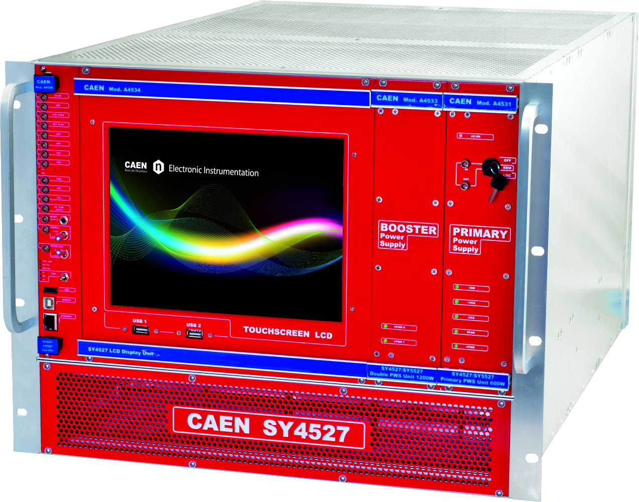
SY4527: A large experimental system. This 19” wide / 8U high mainframe can house up to 16 HV/LV boards. It offers a power output from 600W up to a maximum of 4200W, depending on installed Power Supply Units and display type. Local control is optionally available via a 10.4” or 5.7” LCD Touchscreen.
-
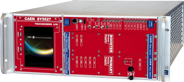
SY5527: A more compact laboratory version. This 19” wide / 4U high mainframe can house up to 6 HV/LV boards. Its power output ranges from 600W up to a maximum of 1800W, depending on Power Supply Units. Optional local control is available via a 5.7” LCD Touchscreen.
-
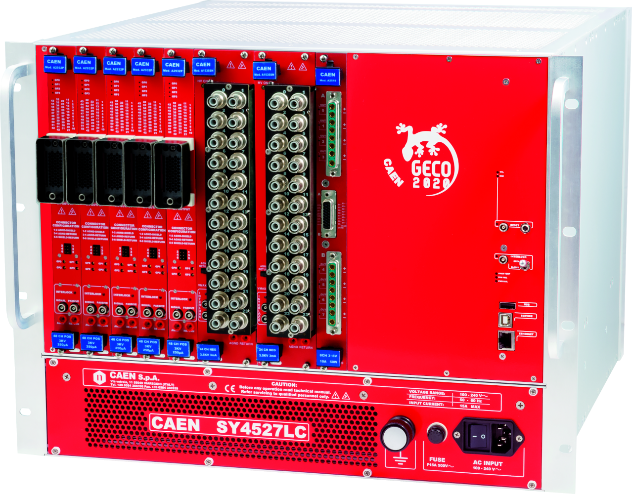
SY4527LC: A cost-effective alternative with a shorter depth (~20cm compared to standard SYx527). This 19” wide / 8U high mainframe houses up to 10 boards and includes a 600W power supply. It does not include an LCD display. It is fully compatible with SY4527 and SY5527 boards.
-
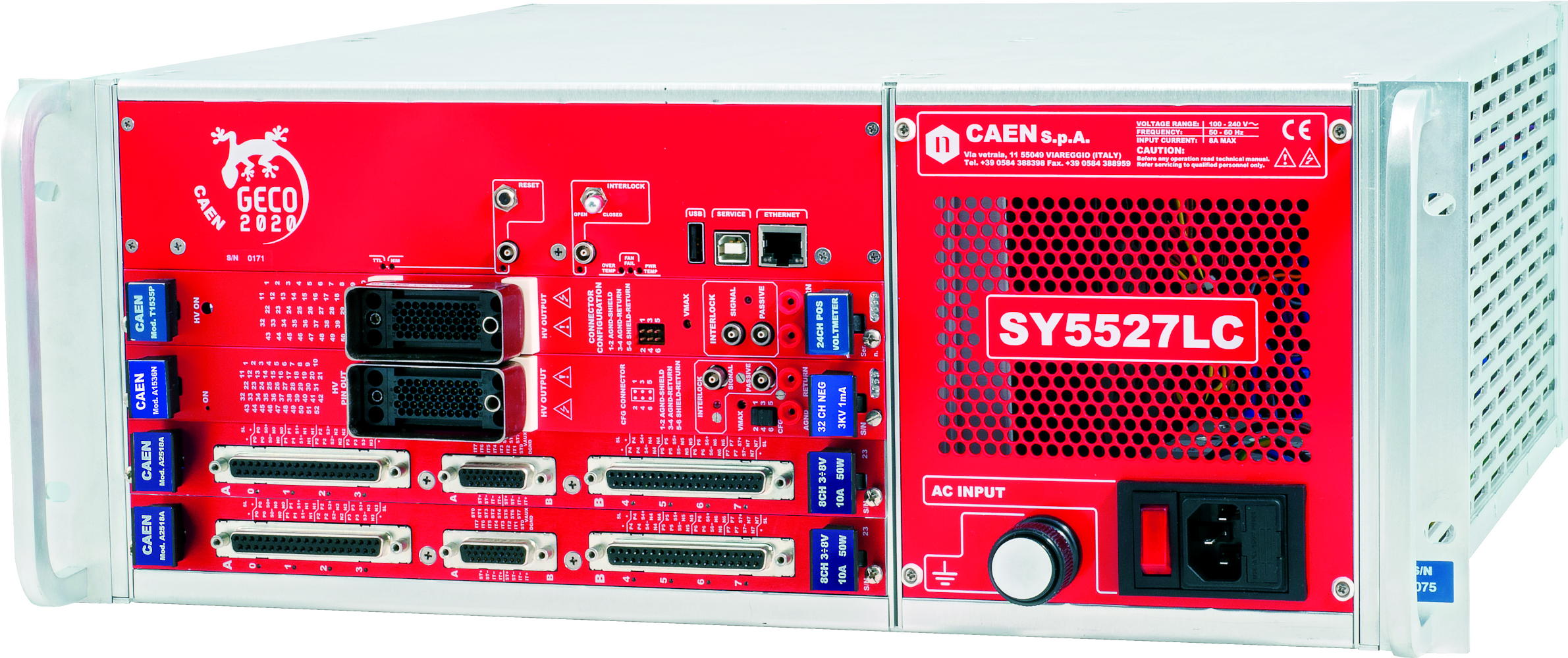
SY5527LC: Also a cost-effective, shorter depth alternative (~20cm compared to standard SYx527). This 19” wide / 4U high mainframe houses up to 4 boards and includes a 400W power supply. It does not include an LCD display. It is fully compatible with SY4527 and SY5527 boards.
All systems offer modular design for simplified upgrades and maintenance and can be controlled remotely via Ethernet.
You also may be interested in…
SY4527
SY4527LC
SY5527
SY5527LC
Request a Quote

Compare

|
Image
|
Name
|
No. of Channels
|
Max Output <br>V
|
Max Output <br>I
|
Vset/Vmon Resolution
|
Iset/Imon Resolution
|
Max. Ramp Up/Down Rate
|
Ripple Typ.
|
Connectors
|
Max Power per Channel
|
Grounding
|
Polarity
|
|
|
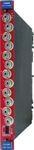
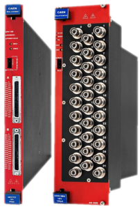
A1538D |
12 |
1500 V |
10 mA |
50 mV |
200 nA |
500 V/s |
< 20 mVpp |
SHV |
12 W |
Common Floating Return |
Neg / Pos |
|
|
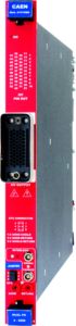
A1515B |
14 / 16 |
1000 V / 1400 V |
1 / 0.1 mA or 3 / 0.3 mA selectable |
20 mV |
Iset: 20 nA Imon: 1 / 0.1 nA |
100 V/s |
< 10 mVpp (CM) <br>< 5 mVpp (DM) |
Radiall 52 / REDEL 51 |
0.7 W |
Full Floating |
- |
|
|
A7038 |
32 / 48 |
1000 V |
0.1 mA |
20 / 2 mV |
2 nA / 500 pA |
500 V/s |
< 10 mVpp |
SHV / DB37 |
0.1 W |
Common Floating Return |
Neg / Pos |
|
|
AG538D |
12 |
1500 V |
10 mA |
50 mV |
200 nA |
500 V/s |
< 20 mVpp |
SHV |
12 W |
Common Ground |
Neg / Pos |
Technical Specifications
|
No. of Channels |
16 or 14 (Floating Return) A1515BTG, A1515BQG, A1515BCG, A1515BTGHP: channel are grouped in two “complex” channels |
||||||||||||
|
Output Voltage |
|
||||||||||||
|
Polarity |
Floating 5 kV |
||||||||||||
|
Max. Output Current |
|
||||||||||||
|
Voltage Set Resolution |
20 mV |
||||||||||||
|
Voltage Monitor Resolution |
20 mV |
||||||||||||
|
Current Set Resolution |
20 nA |
||||||||||||
|
Current Monitor Resolution |
|
||||||||||||
|
VMAX software |
0÷1 kV or 0÷1.3 kV (A1515BCG), settable for each channel or 0÷1.4 kV (x A1515BV) |
||||||||||||
|
VMAX software resolution |
1 V |
||||||||||||
|
Ramp Up/Down |
1÷100 Volt/sec, 1 Volt/sec step, settable for each channel |
||||||||||||
|
Trip |
Max. time an “overcurrent” is allowed to last (seconds); common to all channels in a “complex channel”. A channel in “overcurrent” works as a current generator; output voltage varies in order to keep the output current lower than the programmed value. “Overcurrent” lasting more than set value, causes the channel to “trip”. Output voltage will drop to zero at the Ramp-down rate; in this case the channel is put in the off state. If trip= INFINITE, “overcurrent” lasts indefinitely. TRIP range: 0 ÷ 999.9 s; 1000 s = Infinite. Step = 0.1 s |
||||||||||||
|
Voltage Ripple |
|
||||||||||||
|
Voltage Monitor vs. Output Voltage Accuracy |
0.2% ± 0.2V ± 50 ppm/°C |
||||||||||||
|
Voltage Set vs. Output Voltage Accuracy |
0.2% ± 0.2V ± 50 ppm/°C |
||||||||||||
|
Imon det vs Output current accuracy |
|
||||||||||||
|
Imon real vs Current set Accuracy |
2% ±100 nA |
||||||||||||
|
Power consumption |
|
||||||||||||
|
Maximum output power |
|
Footer