12-bit 5 GS/s
742 Digitizer Family
Overview
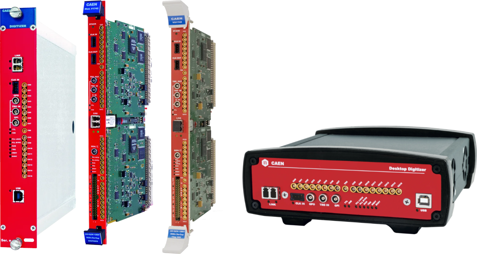
The 742 is the Switched Capacitor Digitizer family, based on the DRS4 chip by PSI, with the highest sampling frequency (5GS/s) and channel density. It can record very fast signals from scintillators coupled to PMTs, Silicon Photomultipliers, APD, Diamond detectors and others, and save them with high efficiency and precision for advanced timing analysis. The 742 family has an additional channel (two channels in case of VME boards) which can be used as time reference for time of fight measurements. The resolution of this kind of measurements can reach up to 50 ps.
The analog inputs are continuously sampled by the 1024 capacitive cells in the DRS4 chip at a frequency that is software selectable among 5 GS/s, 2.5 GS/s, 1 GS/s and 750 MS/s. Once the trigger condition is met, the capacitors are released, data is converted by a 12-bit ADC at a lower frequency and stored into a digital memory buffer. As the sampling and the analog-to-digital conversion are not simultaneous, a dead-time is introduced, during which the board cannot accept other triggers. Multiple boards can be synchronized to build up complex systems.
The acquisition is fully controlled by the WaveDump software, which manages the settings, plots and saves the waveforms. Libraries and demo software in C and LabView are available for integration and customization of specific acquisition systems.
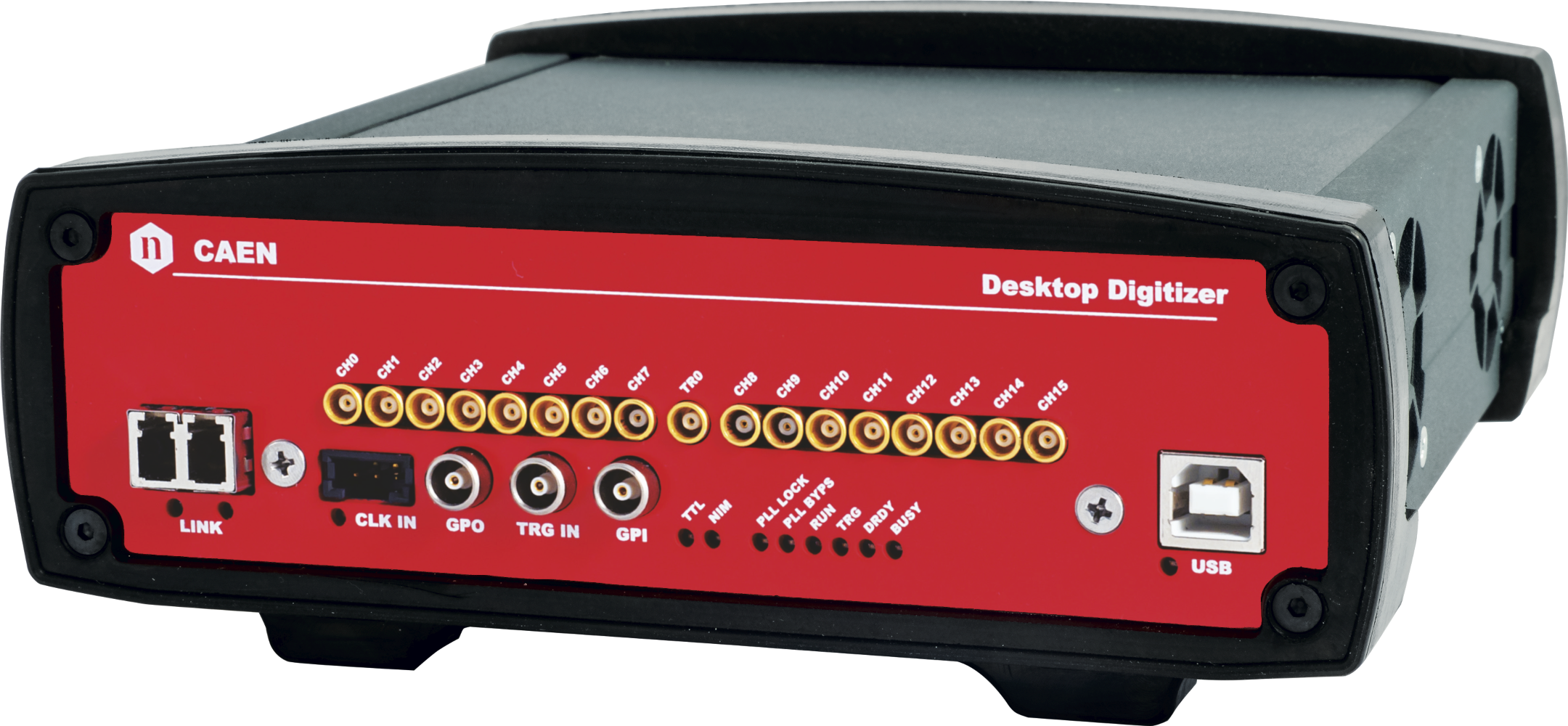
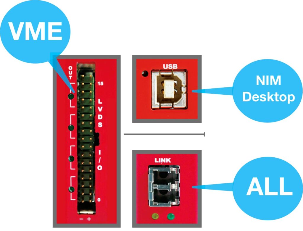
742 family comes in three form factors: VME (32 input channels + 2 additional channels), NIM (16 input channels + 1 additional channel) and Desktop (16 input channels + 1 additional channel). The communication to and from the board is provided through the following interfaces: USB (Desktop and NIM form factors), VMEbus (VME form factor), and Optical Link (all form factors)
Highlights
-
12-bit @ 5 GS/s, 1024 samples per event
-
5, 2.5, 1 and 0.75 GS/s software selectable sampling frequencies
-
Analog inputs on MCX coaxial connectors
-
VME64/VME64X (32+2 ch.), NIM (16+1 ch.) and Desktop (16+1 ch.) modules
-
1 Vpp input dynamic range with programmable DC offset adjustment
-
VME, USB and Optical Link communication interfaces
-
Multi-board synchronization features
-
Daisy chain capability
-
Demo software tools, C and LabVIEW libraries, Readout Software
12-bit 5 GS/s Models
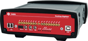
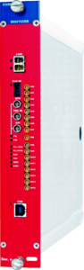
DT5742
16+1 Channel 12 bit 5 GS/s Switched Capacitor Digitizer
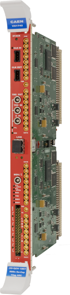
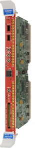
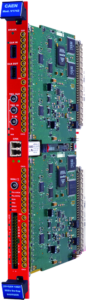
VX1742
32+2 Channel 12bit 5 GS/s Switched Capacitor Digitizer
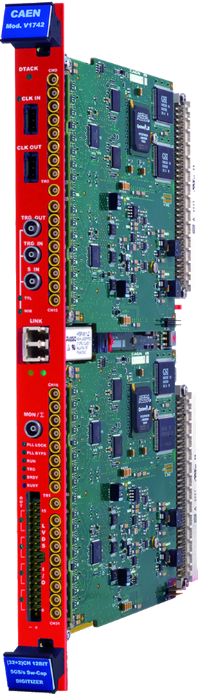
V1742
32+2 Channel 12bit 5 GS/s Switched Capacitor Digitizer
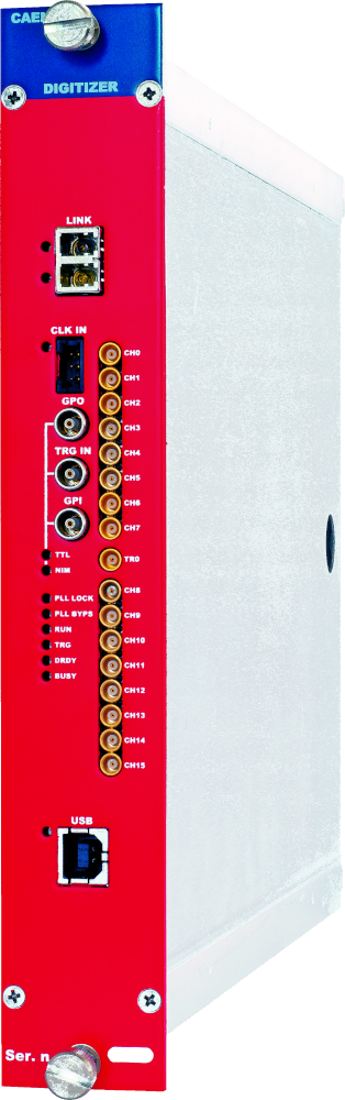
N6742
16+1 Channel 12bit 5 GS/s Switched Capacitor Digitizer
Image |
Name
|
Package |
No. of Channels |
Max Sampling Rate (MS/s) |
Bandwidth (MHz) |
Full Scale Range (V) |
Resolution (bits) |
Board Memory (Samples/ch) |
Analog Input Connectors |
CAEN firmware |
Open FPGA | |
 |
DT5742 |
Desktop |
16 + 1 |
5000 (Based on DRS4 chip: 5 GS/s Switched Capacitor Array) |
500 |
1 |
12 |
0.128 / 1 |
MCX |
D-WAVE |
NO | |
 |
VX1742 |
VME64X |
32 + 2 |
5000 (Based on DRS4 chip: 5 GS/s Switched Capacitor Array) |
500 |
1 |
12 |
0.128 / 1 |
MCX |
D-WAVE |
NO | |
 |
V1742 |
VME |
32 + 2 |
5000 (Based on DRS4 chip: 5 GS/s Switched Capacitor Array) |
500 |
1 |
12 |
0.128 / 1 |
MCX |
D-WAVE |
NO | |
 |
N6742 |
NIM |
16 + 1 |
5000 (Based on DRS4 chip: 5 GS/s Switched Capacitor Array) |
500 |
1 |
12 |
0.128 / 1 |
MCX |
D-WAVE |
NO |
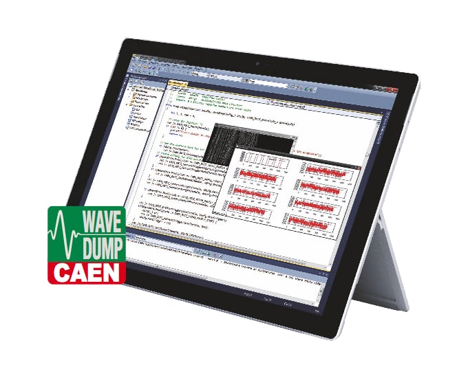
WaveDump
Open Source Acquisition Software for Developers
WaveDump is a basic console application supporting digitizers running Waveform Recording firmware. WaveDump allows the user to program a single board (according to a text configuration file containing a list of parameters and instructions), to start/stop the acquisition. It is then possible to read the data, display the readout and trigger rate. Moreover, it is also possible to apply some post-processing (e.g. FFT and amplitude histogram), save data into a file and also plot the waveforms using Gnuplot third-party graphical utility.
WaveDump is a very helpful example of C code demonstrating the use of libraries and methods for an efficient readout and data analysis. Expert users can start with this demo to write their own acquisition software to exploit the full potentialities of the digitizers. Source files and the VS project are available for free download. Available Firmware:
Interfaces & I/O
USB An USB 2.0 link is provided in NIM and Desktop form factors for an easy data readout VME Digitizer can be controlled via USB using the CAEN V3718 VME-USB2.0 Bridge
Optical Link An Optical link is provided in any form factor for high performance data readout through CAEN proprietary daisy-chainable CONET communication protocol. it is possible to connect up to 8/32 ADC modules to a single Optical Link Controller (Mod. A4818/A3818)
Digital I/O Digital I/Os are provided in VME boards that can be used for individual trigger propagation to external trigger logic. This feature makes VME form factor ideal to scale up the acquisition channels where a global trigger generation is mandatory.
Footer