

Highlights
-
EASY Subsystem Power Supply Module
-
Magnetic field and radiation tolerant
-
12 floating 4 ÷ 14 V / 5 A channels (positive polarity)
-
APP30 connectors
-
45 W maximum output power per channel
-
VMax and IMax set by trimmer for each channel
-
On/Off for each channel
-
Channels individually controlled and protected
-
Voltage Drop compensation via sense wires
-
Interlock capability
-
48 V Service local and remote on/off
Overview
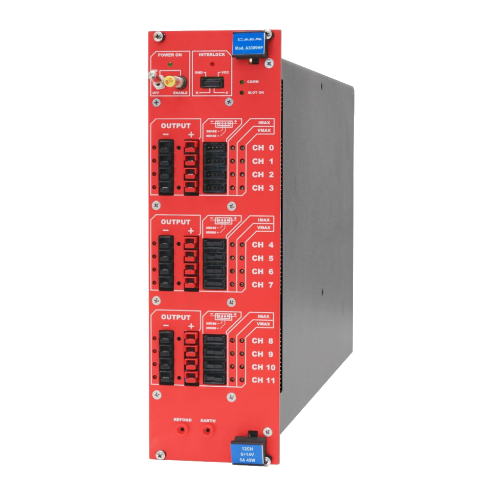
The CAEN Mod.A3009H 12 Channel 14 V / 5 A Power Supply Board is developed for operation in magnetic field and moderate radioactive environment. One A3009H houses 12 positive 14 V / 5 A / 45 W maximum output power, channels. The connector output voltage range is 6 ÷ 14 V with 5 mV monitor resolution; channel control includes various alarms and protections. A 11.8V ± 0.1V hardware limit is available on request. The board is provided with Remote Sensing Lines to compensate for the voltage drop over the connection cables.
|
APP30 connector APP30 1317G4 type connector for Mod.A3009HP |
Consult our connectors reference page for technical information.
Safety features allows the module to perform as a current generator and includes:
|
Channels |
can be enabled or disabled through the Global Interlock logic. |
|
Overvoltage and Undervoltage warning |
when the output voltage differs from the programmed value by more than 3% of voltage full scale range. |
|
Overcurrent detection |
When a channel attempts to exceed the programmed current limit, it signalled to be in “overcurrent” and enter in a TRIP status. The output voltage is varied to keep the current below the programmed limit for a programmable TRIP time, then the channel is switched off. If TRIP is set to “constant current mode”, the channel behaves like a current generator. |
|
Hardware VMAX and IMAX |
Maximum output voltage and maximum current value can be fixed via software with 5 mV resolution and the output voltage can not be programmed beyond this value. |
Request a Quote

Compare

|
Image
|
Name
|
No. of Channels
|
Connectors
|
No. max of boards per crate
|
Width (slots)
|
Max power per channels
|
Iset/Imon resolution
|
Vset/Vmon resolution (mV)
|
Current Full Scale (A)
|
Voltage full Scale (V)
|
Max Ripple (mVpp)
|
|
|
A3009B |
12 |
Screw lock connectors |
5 |
4 |
45 W |
10 mA |
5 |
9 |
2 ÷ 8 |
20 |
|
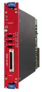
|
A3602 |
3 |
DB37 |
10 |
2 |
35 W |
10 mA |
5 |
5 |
2 ÷ 7 |
5 |
|
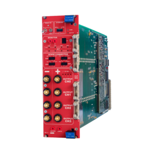
|
A3025B |
4 |
Brass hexagon head bolt |
5 |
4 |
150 W |
100 mA |
5 |
25 |
2 ÷ 8 |
10 |
|
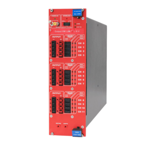
|
A3009 |
12 |
APP 1317G4 |
5 |
4 |
45 W |
10 mA |
5 |
9 |
2 ÷ 8 |
20 |
|
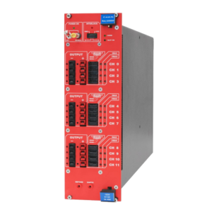
|
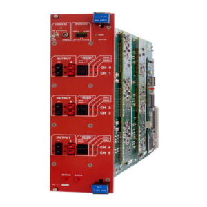
A3009H |
12 |
APP 1317G4 |
5 |
4 |
45 W |
10 mA |
5 |
9 |
6 ÷ 14 |
20 |
|
|
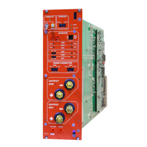
A3016 |
6 |
APP 1317G4 |
5 |
4 |
90 W |
10 mA |
5 |
16 |
2 ÷ 8 |
20 |
|
|
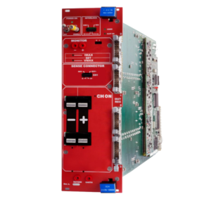
A3050B |
2 |
Brass hexagon head bolt |
5 |
4 |
300 W |
100 mA |
5 |
50 |
2 ÷ 8 |
10 |
|
|
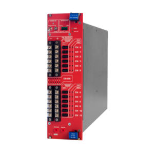
A3100 |
1 |
APP PC5933T |
5 |
4 |
600 W |
100 mA |
5 |
100 |
2 ÷ 8 |
10 |
|
|
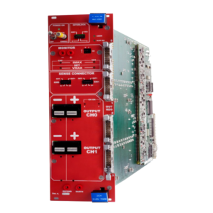
A3009HB |
12 |
Screw lock connectors |
5 |
4 |
45 W |
10 mA |
5 |
9 |
6 ÷ 14 |
20 |
|
|
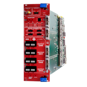
A3050 |
2 |
APP PC5933T |
5 |
4 |
300 W |
100 mA |
5 |
50 |
2 ÷ 8 |
10 |
|
|
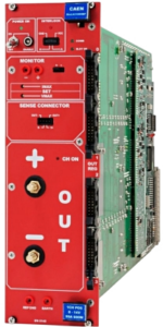
A3025 |
4 |
APP PC5933T |
5 |
4 |
150 W |
100 mA |
5 |
25 |
2 ÷ 8 |
10 |
|
|
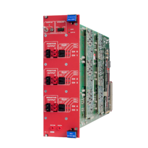
New A3100HBP |
1 |
Brass hexagon head bolt |
5 |
4 |
600 W |
100 mA |
10 |
50 |
8 ÷ 14 |
10 |
|
|
A3006 |
6 |
APP 1317G4 |
5 |
4 |
90 W |
10 mA |
10 |
6 |
4 ÷ 16 |
20 |
|
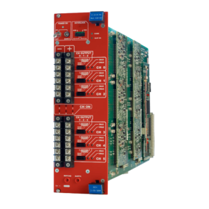
|
A3016B |
6 |
Brass hexagon head bolt |
5 |
4 |
90 W |
10 mA |
5 |
16 |
2 ÷ 8 |
20 |
|
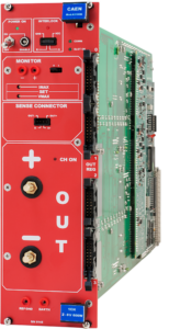
|
A3100B |
1 |
Brass hexagon head bolt |
5 |
4 |
600 W |
100 mA |
5 |
100 |
2 ÷ 8 |
10 |
Technical Specifications
|
No. of Channels |
12, APP30 connectors |
|
Polarity |
Positive; full floating (return individually insulated with respect to earth) |
|
Output Voltage |
6 ÷ 14 V (connector output) 11.8V ± 0.1V hardware limit available on request; a label on the front panel indicates the hardware voltage limit installation |
|
Max. Output Current |
5 A |
|
Voltage Set/Monitor Resolution |
5 mV |
|
Current Set/Monitor Resolution |
10 mA |
|
VMAX hardware |
6 ÷ 14 V |
|
VMAX software |
6 ÷ 14 V |
|
VMAX software resolution |
5 mV |
|
Ramp Up |
from 0.1 V/s to 400 V/s with 0.1 V/s steps |
|
Voltage Ripple |
<20 mV pp on 10 µF // 0.1 µF 10 Hz-15 MHz |
|
Voltage Monitor vs. Output Voltage Accuracy |
max. ±30 mV ±0.3% of reading |
|
Voltage Set vs. Output Voltage Accuracy |
max. ±30 mV ±0.3% of reading |
|
Current Monitor vs. Output Current Accuracy |
± 0.05A ± 2% of reading |
|
Current Set vs. Output Current Accuracy |
± 0.05A ± 2% of reading |
|
Load Regulation |
± 0.3 % (with sense wires) ± 2 % (without sense wires) |
|
Output Power (per Channel) |
45 W |
|
Test Set Up |
cable: length = 20~30m; diam.= 10 mm (for both output and return) with sense wires connected test load: 250÷2000 W (nominal) load capacitance: 100 µF electrolytic // 100 nF ceramic (// to the load) |
|
Weight |
5.5 kg |
Footer