
Highlights
-
3 programmable ranges: 100 ps LSB (19 bit resolution), 200 ps LSB (19 bit) and 800 ps LSB (17 bit)
-
ECL/LVDS inputs automatically detected
-
5 ns Double Hit Resolution
-
Leading and Trailing Edge detection
-
Trigger Matching and Continuous Storage acquisition modes
-
32 k x 32 bit output buffer
-
MBLT, CBLT and 2eSST data transfer
-
Multicast commands
-
Live insertion
-
Libraries, Demos (C and LabView) and Software tools for Windows and Linux
Overview
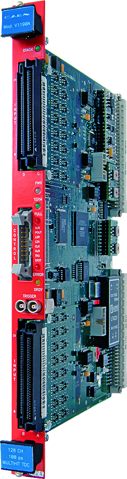
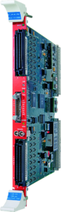
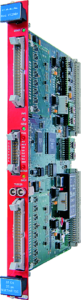
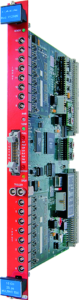
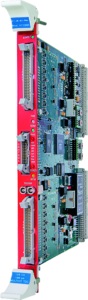
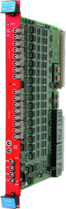
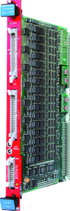
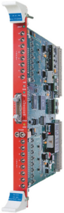
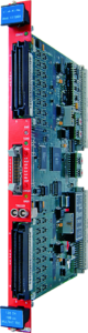
The CAEN Mod. V1190A-2eSST is a 128 channel Multihit TDC, housed in a 1-unit wide VME 6U module. The unit features High Performance Time to Digital Converter chips developed by CERN. LSB can be set at:
-
100 ps (19 bit resolution, 52 µs FSR),
-
200 ps (19 bit, 104 µs FSR)
-
800 ps (17 bit, 104 µs FSR)
The channels can be enabled for the detection of hits rising/falling edges or for their width measurement (both the edges’ timing, and the hit width can be measured with the selected resolution). For each channel there is a digital adjustment for the zero-ing of any offsets. The data acquisition can be programmed in “Events” (“Trigger Matching Mode”, with a programmable time window) or in “Continuous Storage Mode”. Both ECL and LVDS input signals are supported.
The module programming is performed via a microcontroller that implements a high-level user friendly interface. The VME interface allows the module to work in A24 and A32 addressing modes. The board houses a 32 k x 32 bit deep Output Buffer that can be readout via VME in a completely independent way from the acquisition itself.
The device supports MBLT, CBLT and 2eSST readout modes. Live insertion is also supported.

You also may be interested in…
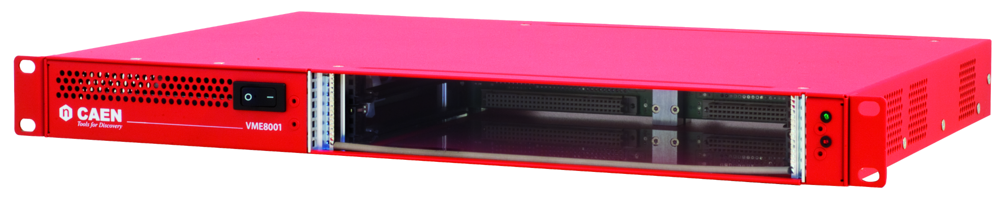
VME8001
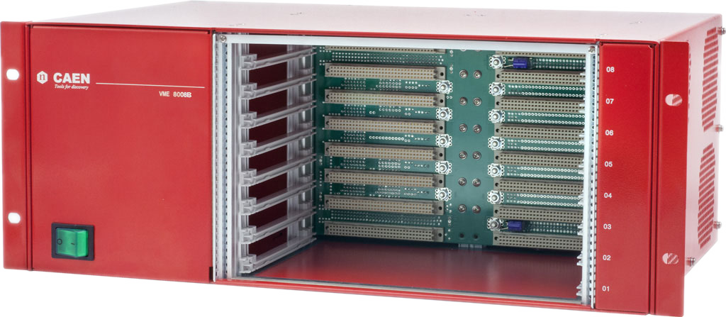
VME8008B
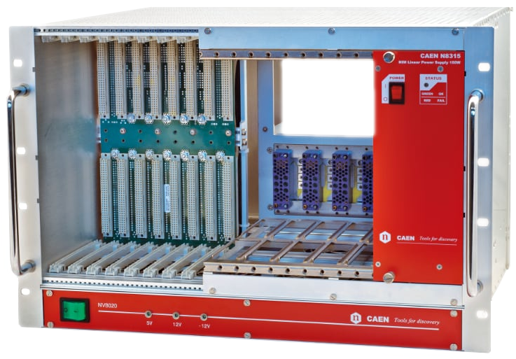
NV8020A
VME8100
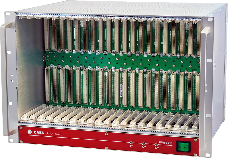
VME8011
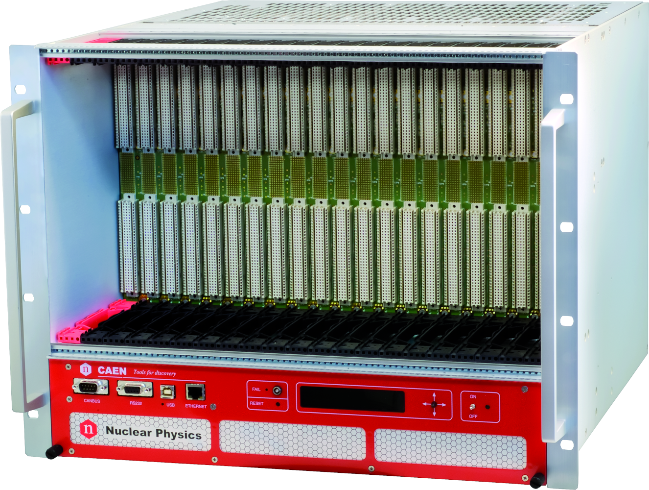
VME8200
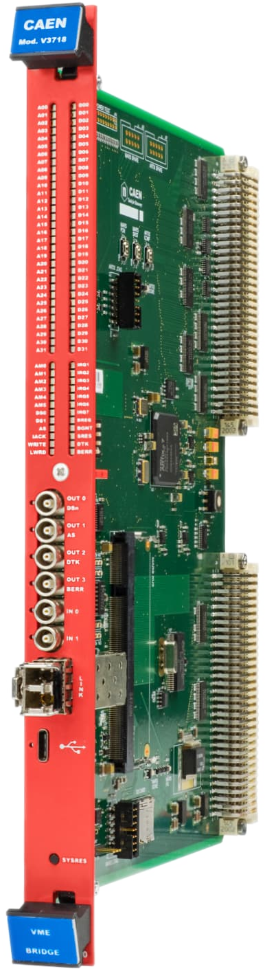
V3718
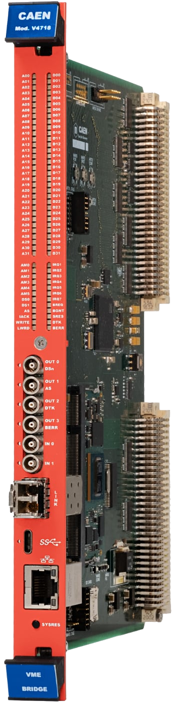
V4718
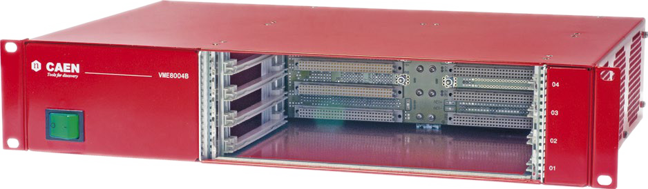
VME8004B
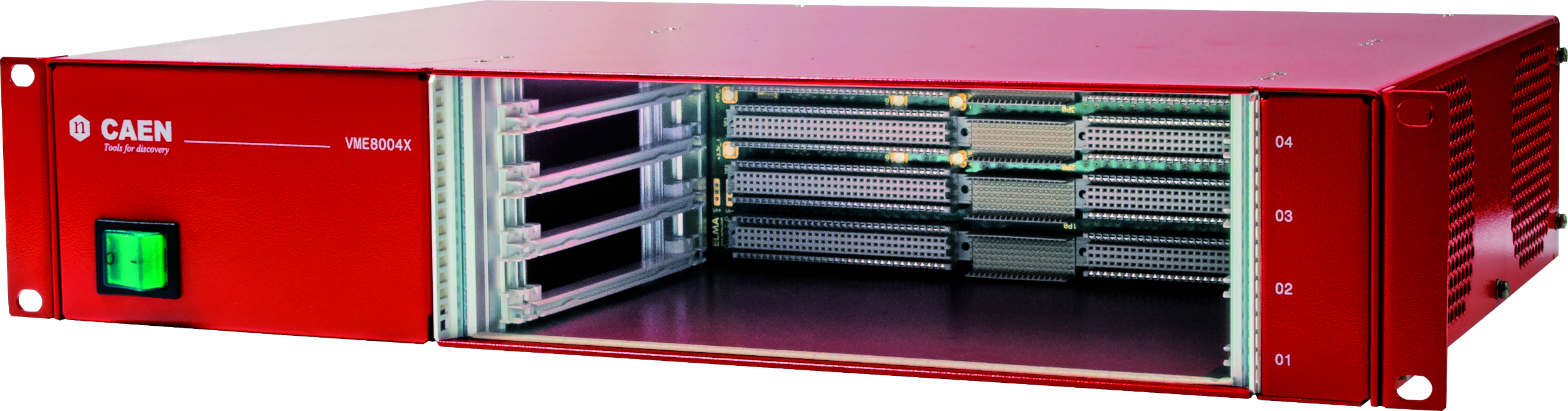
VME8004X
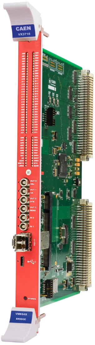
VX3718
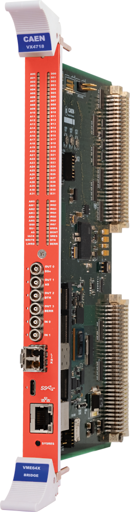
VX4718
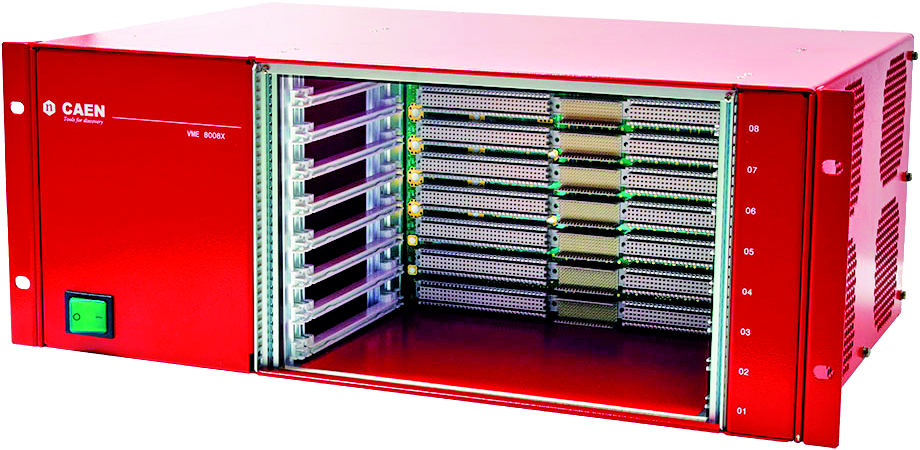
VME8008X
Request a Quote

Compare

|
Image
|
Name
|
Package
|
No. of Channels
|
Resolution (bit)
|
Type
|
Conversion Time (µs)
|
LSB (ps)
|
Full Scale Range (µs)
|
Input Type
|
Connectors
|
|
|
VX1190A-2ESST |
VME64X |
128 |
19 / 17 |
Multihit Digital TDC |
- |
100 / 200 / 800 |
52 / 104 |
ECL / LVDS |
Robinson Nugent Flat |
|
|
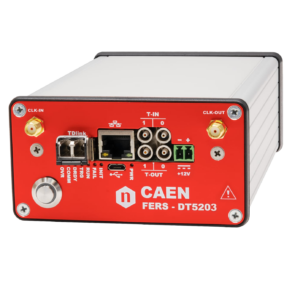
DT5203 |
Desktop |
64 |
26 |
Multihit Digital TDC |
- |
3.125 |
52 |
LVDS |
1 edge connector type HSEC8-170 |
|
|
V1290A-2ESST |
VME |
32 |
21 |
Multihit Digital TDC |
- |
25 |
52 |
ECL / LVDS |
Std. Flat |
|
|
V1290N-2ESST |
VME |
16 |
21 |
Multihit Digital TDC |
- |
25 |
52 |
NIM |
LEMO |
|
|
VX1290A-2ESST |
VME64X |
32 |
21 |
Multihit Digital TDC |
- |
25 |
52 |
ECL / LVDS |
Std. Flat |
|
|
V775N |
VME |
16 |
12 |
Analog TDC |
2.8 |
35 / 300 |
0.14 / 1.2 |
NIM |
LEMO |
|
|
A5203 |
Desktop |
64/128 |
26 |
Multihit Digital TDC |
- |
3.125 |
52 |
LVDS |
1 edge connector type HSEC8-170 |
|
|
V775 |
VME |
32 |
12 |
Analog TDC |
5.7 |
35 / 300 |
0.14 / 1.2 |
ECL |
Std. Flat |
|
|
VX1290N-2ESST |
VME64X |
16 |
21 |
Multihit Digital TDC |
- |
25 |
52 |
NIM |
LEMO |
|
|
V1190A-2ESST |
VME |
128 |
19 / 17 |
Multihit Digital TDC |
- |
100 / 200 / 800 |
52 / 104 |
ECL / LVDS |
Robinson Nugent Flat |
Technical Specifications
|
Packaging |
6U-high, 1U-wide VME unit |
|
Inputs |
128 ECL/LVDS inputs, 110 Ohm impedance |
|
Double hit resolution |
5 ns |
|
Acquisition modes |
Trigger Matching Mode; Continuous Storage Mode |
|
Built-in memory |
32 kwords deep Output Buffer |
|
Trigger Window Width |
Programmable from 25 ns to 100 µs |
|
LSB |
800, 200, 100 ps (selectable) |
|
Dynamic Range |
104 µs (200 ps and 800 ps LSB); 52 µs (100 ps LSB) |
|
RMS resolution |
<320 ps @ 800 ps res. <140 ps @ 200 ps res. <80 ps @ 100 ps res. |
|
Integral non linearity |
<0.3 LSB @ 800 ps res. <1 LSB @ 200 ps res. <1 LSB @ 100 ps res. |
|
Differential non linearity |
<0.2 LSB @ 800 ps res. <0.3 LSB @ 200 ps res. <0.5 LSB @ 100 ps res. |
|
Interchannel Isolation |
≤0.7 LSB |
|
Offset spread |
<2 ns |
|
EXT TRIGGER input |
Two LEMO 00 bridged connectors, ECL signal, 110 Ohm |
|
Clock source |
Internal (40 MHz) or External (on Control connector), dip switch selectable |
|
Control inputs |
active-high, differential ECL input signals:
rising-edge active, differential ECL input signals
|
|
Control outputs |
differential ECL output signal: OUT_PROG: control output signal, programmable via the out prog control register |
|
Displays |
DTACK: green LED; lights up at each VME access.PWR: green/red LED; green: power ON, red: failure status.TERM: green LED; control bus termination ON.FULL: red LED; memory full. ERROR: red LED; TDC global error.DRDY: yellow LED; at least one datum in the output buffer |
|
VME |
Addressing modes: A24, A32, MCST Data transfer modes: D16, D32, BLT32, BLT64, CBLT, 2eSST |
Footer