Highlights
-
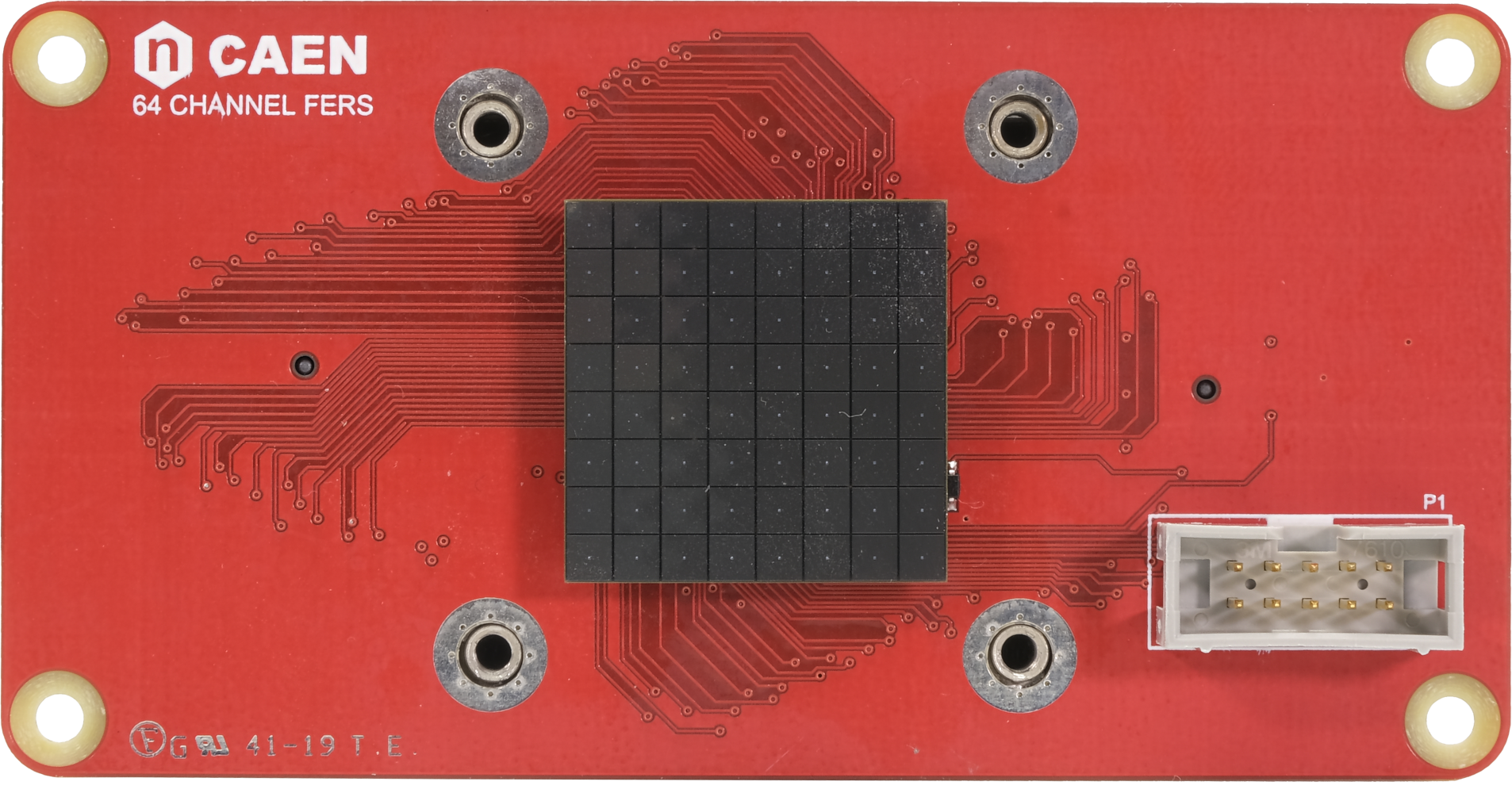
64-ch frontend unit for SiPM readout housing two Weeroc Citiroc-1A ASICs
-
Part of FERS-5200, the CAEN platform for the readout of large arrays of detectors (SiPM, MA-PMTs, Gas Tubes, Si detectors, …)
-
Onboard A7585D SiPM power supply
-
Acquisition modes: Spectroscopy (PHA), Counting, Timing with ToT
-
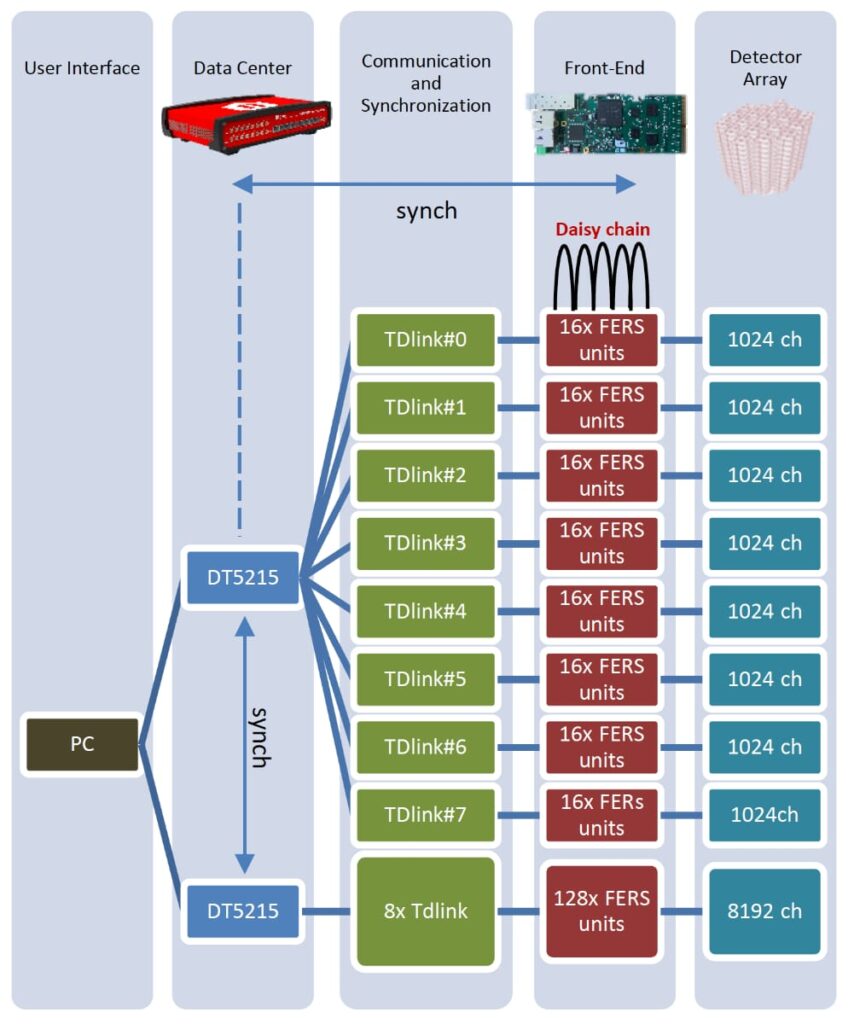
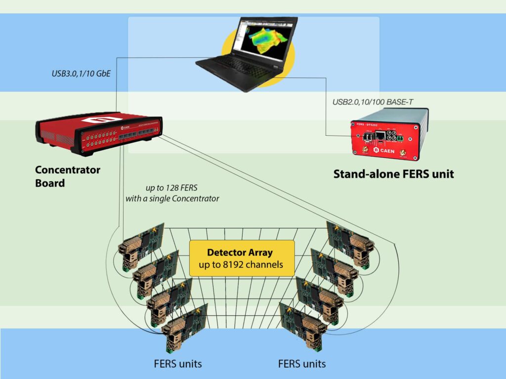
Scalability and easy-sync: from a single standalone FERS unit for prototyping to many thousands of channels, with simple tree network structure. Up to 128 DT5202 units can be managed by a single DT5215 Concentrator Board, i.e. up to 8192 SiPM pixels
-
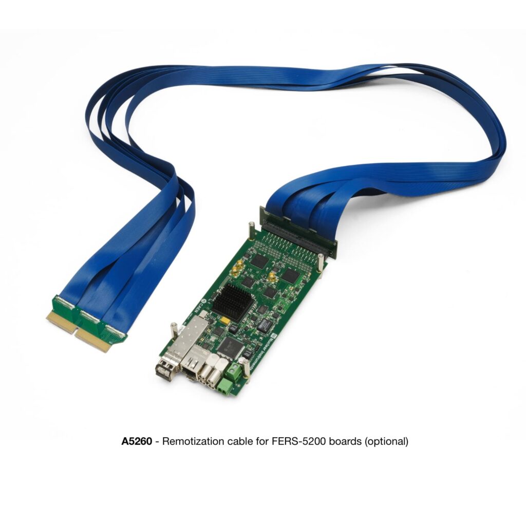
Flexibility: a full range of accessories for sensors remotization
-
Modularity: multiple FERS units can be distributed on large detector volume and managed by a DT5215 Concentrator board
-
Compactness: front-end cards with high channel density ASICs and effective connection to the detector backplane
-
Janus 5202 open source software available for board and DAQ control
-
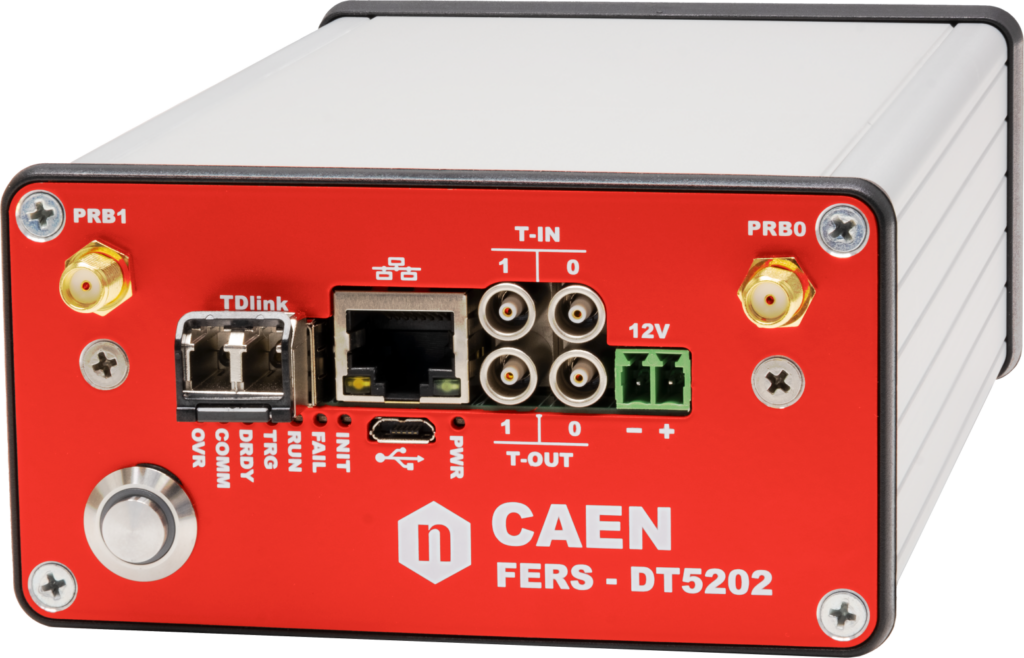
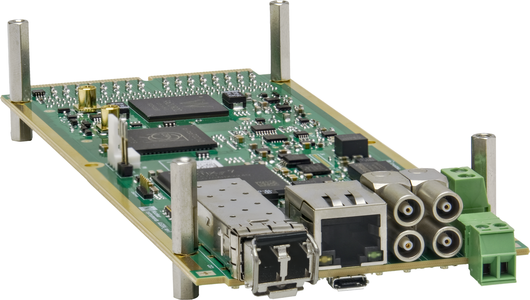
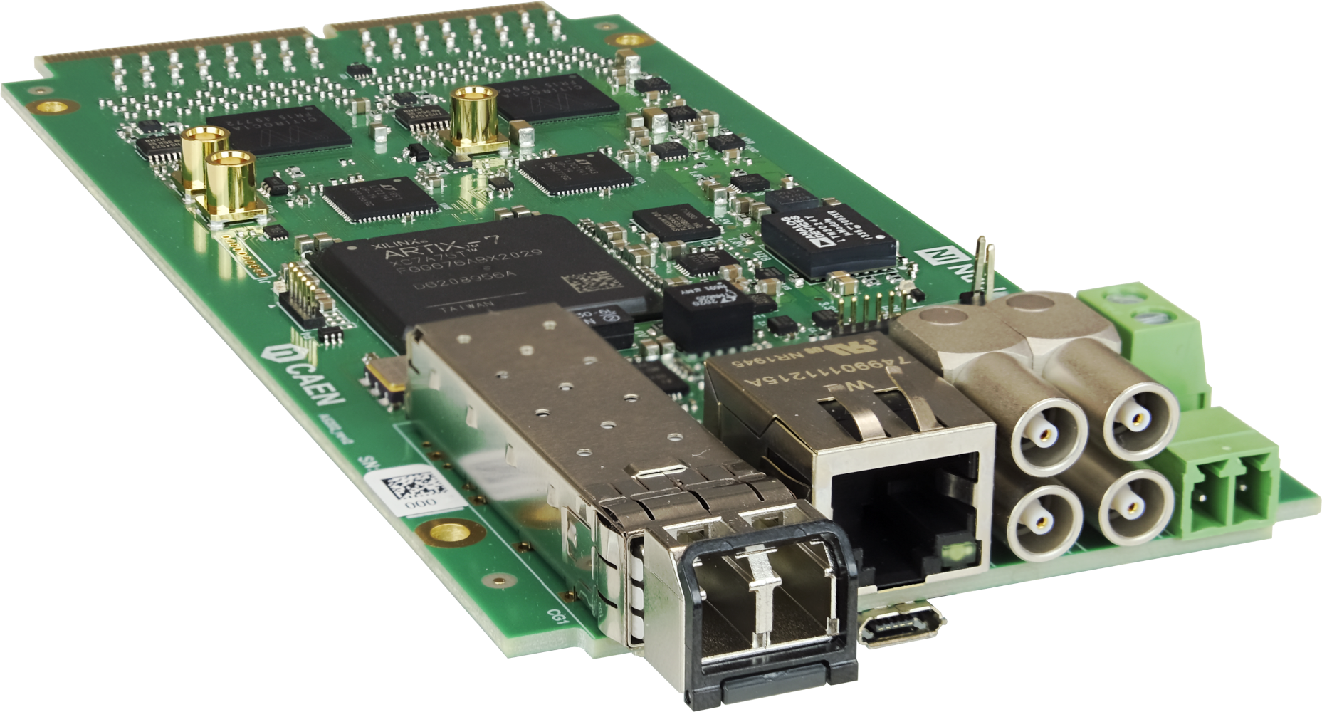
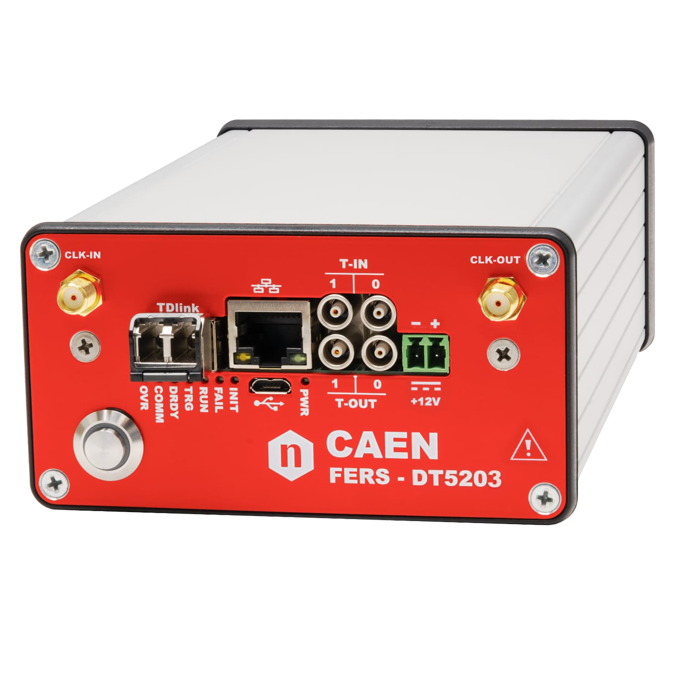
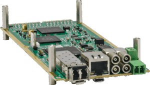
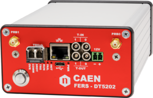
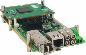
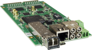
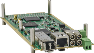
Boxed FERS unit (DT5202) for desktop use or unenclosed FERS unit (A5202) for integration into a custom mechanical frame
Overview
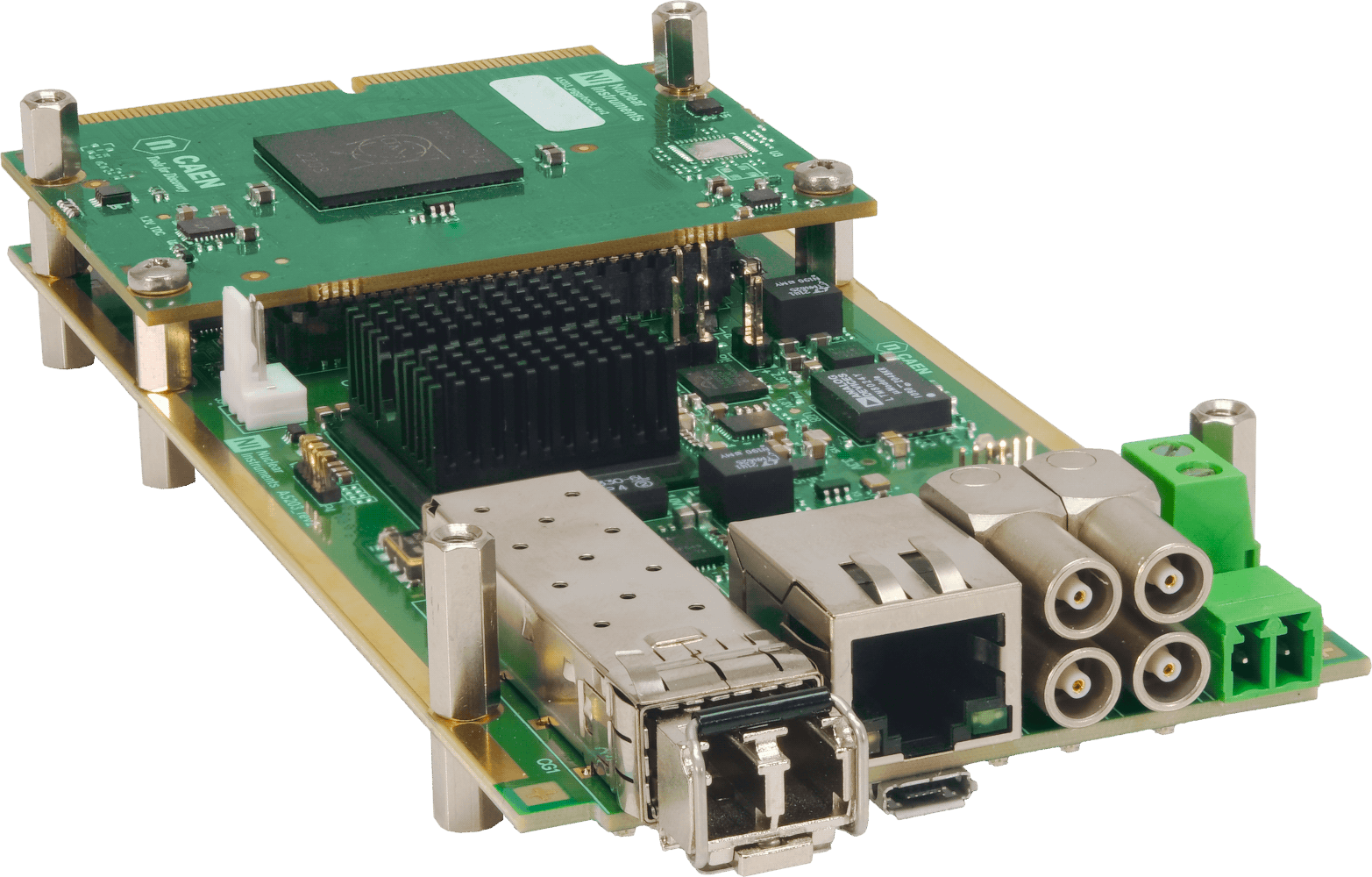
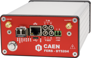
FERS-5200 is a front‐end readout system designed for the readout of large detector arrays, such as SiPMs, multi‐anode PMTs, Silicon Strip detectors, Wire Chambers, GEMs, Gas Tubes and others. FERS‐5200 is a distributed and scalable system, where each unit is a small card that houses 64 or 128 channels with preamplifier, shaper, discriminator, ADC, trigger logic, synchronization, local memory and readout interface. In most cases, the front‐end is based on ASIC chips that allow for high density, cost effective integration of multi‐channel readout electronics into small size and low power modules.
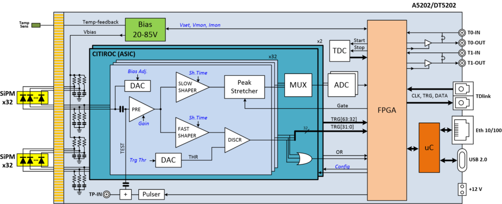
The first FERS‐5200 unit being developed is the A5202 (DT5202 is the boxed version for desktop use) that uses the Citiroc‐1A chip produced by WeeROC for SiPM readout. More precisely, the DT5202 houses two Citiroc‐1A chips (64 readout channels). Each readout channel is composed of a Preamplifier, a Slow Shaper with peak sensing detector and a Fast Shaper followed by a discriminator. Peak sensing values from each Citiroc‐1A are converted sequentially (multiplexed output) by an ADC. The 64 channel self‐triggers (discriminator outputs) can be used for counting, time stamping, to determine the Time over Threshold (ToT) information and also to generate the board bunch trigger that starts the A/D conversion. The DT5202 board is also provided with the A7585D power supply module for biasing the SiPMs and the interfaces for readout, synchronization and control.
The most relevant DT5202 acquisition modes are:
-
Spectroscopy Mode: This mode (also indicated as Pulse Height Analysis, PHA) works with a global (bunch) trigger, either coming from an external source or generated by a combination of the channel self‐triggers. As soon as a trigger is issued, all channels start simultaneously the A/D conversion of the pulse amplitude.
-
Counting Mode: In this mode, the self‐triggers of each channel are individually counted, with the counting intervals defined by an internal periodic gate with programmable width or by an external signal.
-
Timing Mode: This mode generates a list of individual time stamps (referred to a Time Reference signal) optionally combined with the Time over Threshold (ToT) information that gives a rough estimation of the pulse amplitude.
One DT5202 unit can be used stand alone, without any additional hardware, just connected to the PC via USB 2.0 or Ethernet 10/100T.
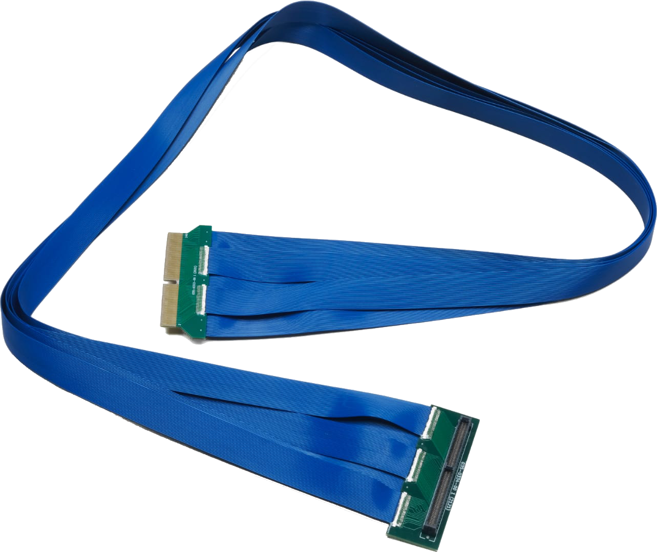
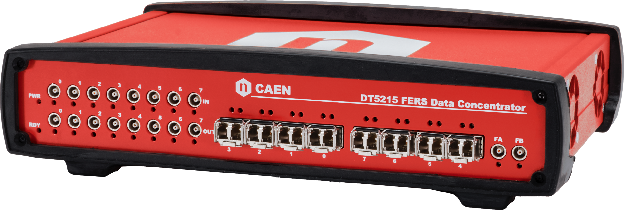
For large readout systems, a flexible and scalable network of units can be created by means of the high speed optical link called TDlink that allows up to 16 FERS‐5200 units to be connected in daisy chain (ring) providing data readout, synchronization between the units and broadcasting of commands (e.g. start/stop run, time resets, etc.). The DT5215 is a data collector board (FERS‐CB) housing 8 TDlink masters that will make it possible to manage up to 128 FERS‐5200 units.
The DT5202 is fully supported by the CAEN Janus 5202 Open Source software on Windows® and Linux®. Janus can run in console mode (C program, without graphics) or connected to a GUI written in Python. The GUI has configuration and run control panels that simplify the data acquisition management. Both console and GUI modes permits to acquire data from multiple boards, manage the event building and timing histograms, display data statistics, plot histograms, and save output, including spectra and list files with the acquired timing data.
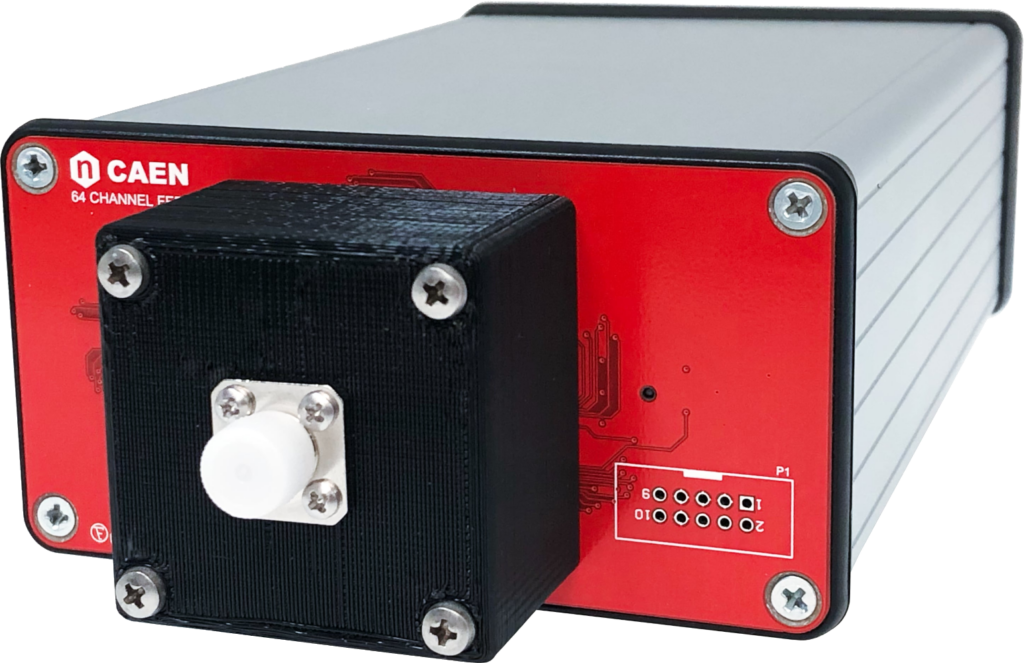
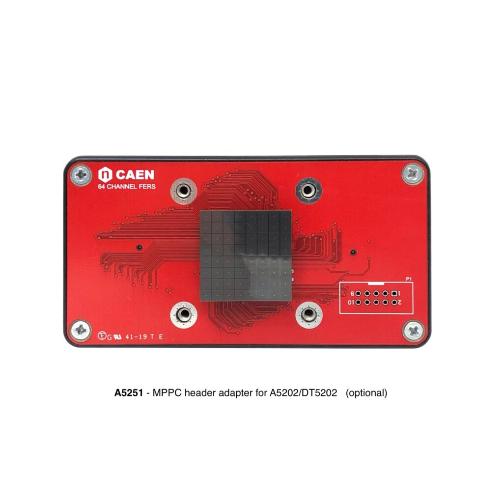
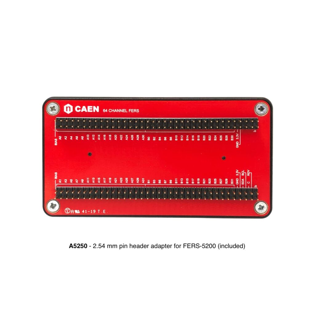
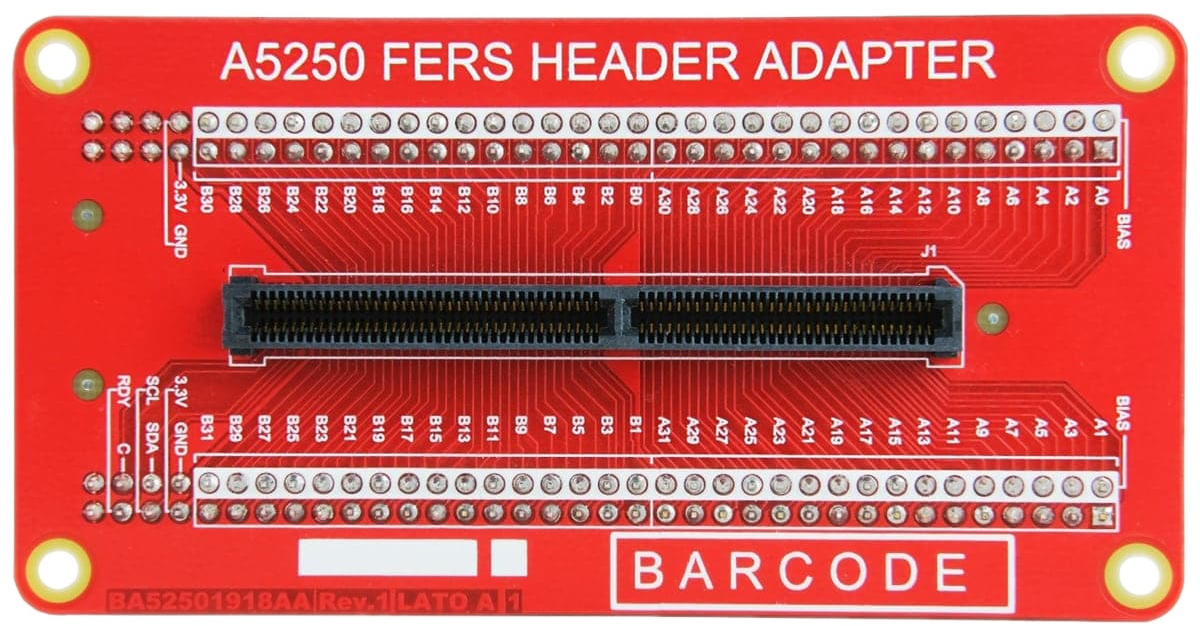
The DT5202 is supplied as standard with the A5250 adapter pre-installed on the rear panel, ensuring a ready-to-use default configuration. If a different compatible adapter is required, it must be ordered separately as an additional item.
A wide range of alternative compatible adapters is available to meet different application needs. View the full list here.


Accessories
A5250
A5251
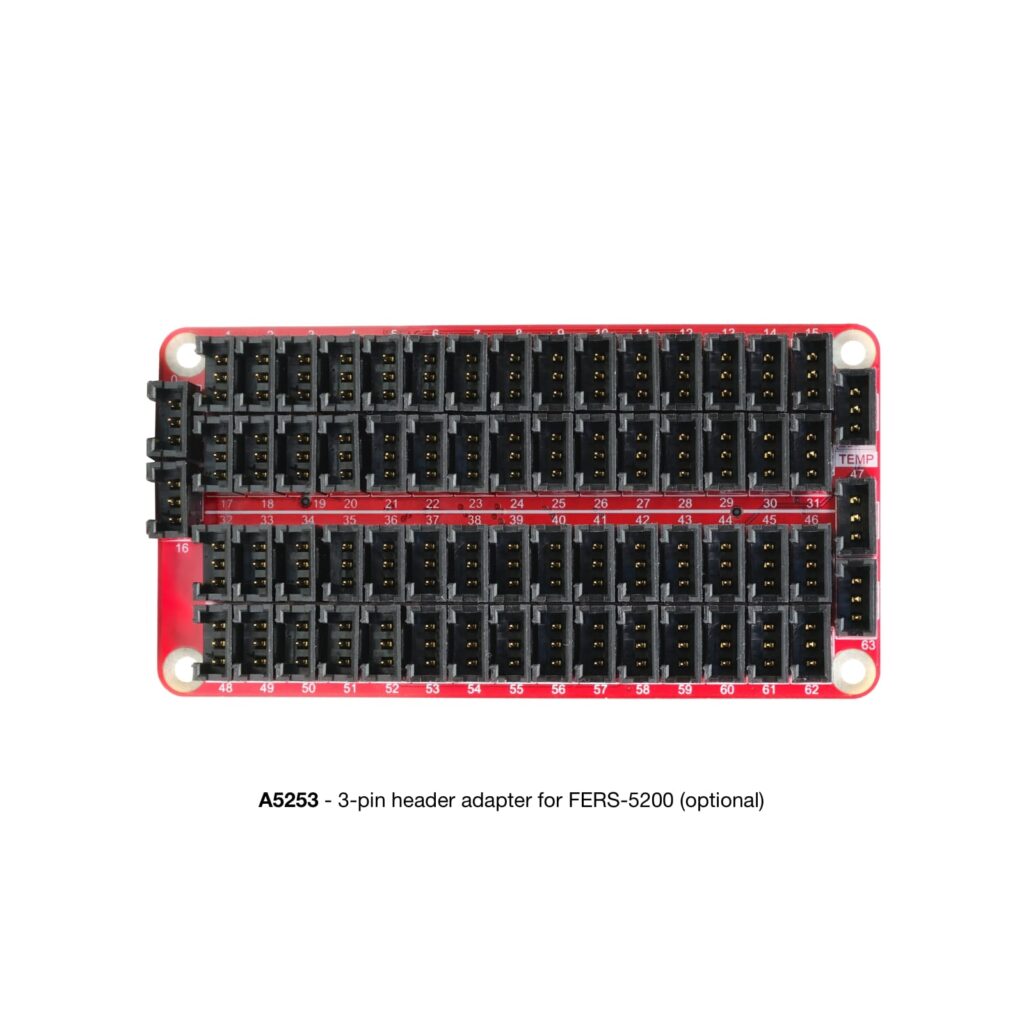
A5253
3-pin header adapter for x5202 & x5204
A5254
A5260
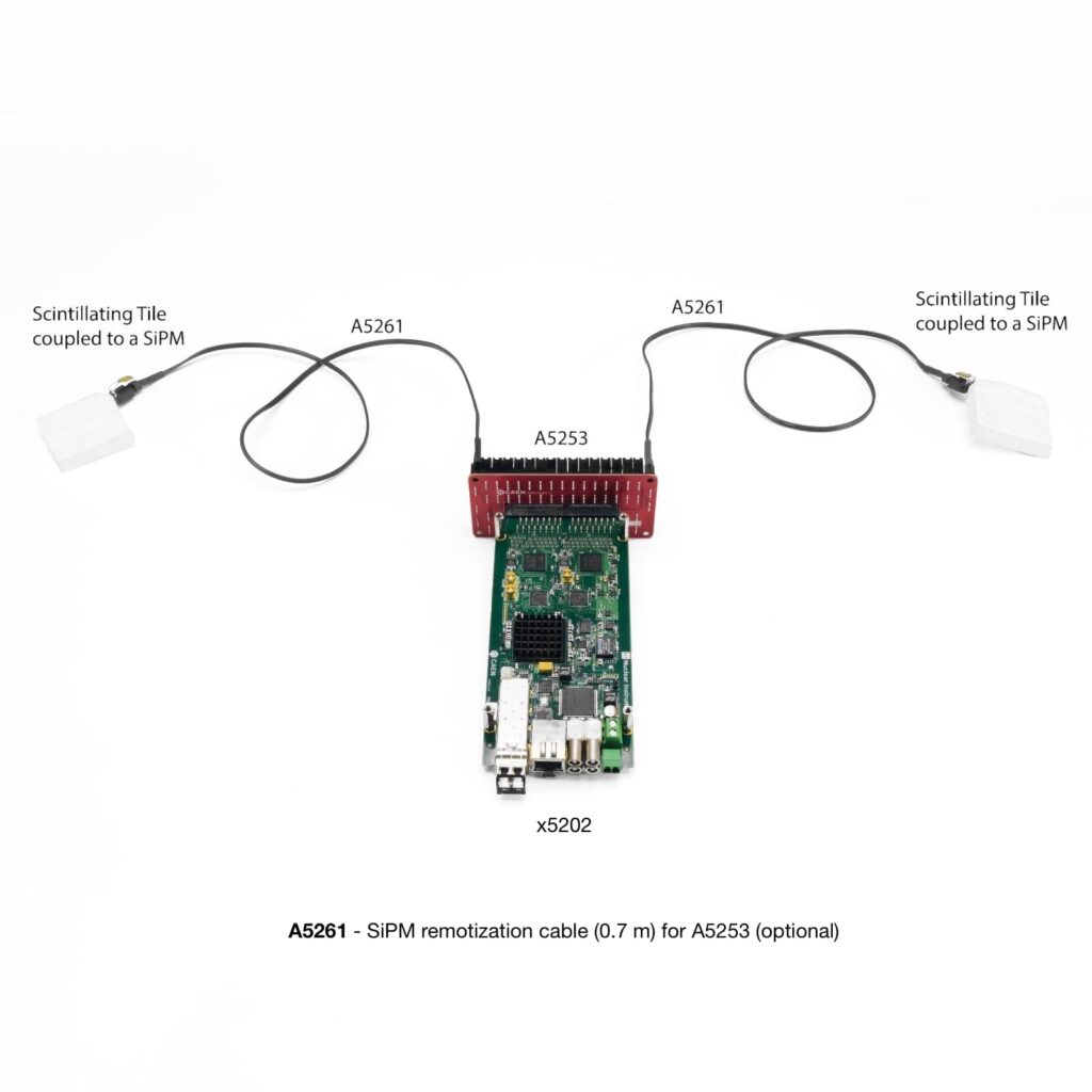
A5261
You also may be interested in…
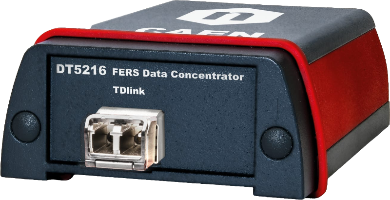
DT5216
A5203
A5204
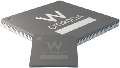
CITIROC 1A
A5202
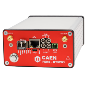
DT5203
DT5215

DT5204
Request a Quote

Compare

|
Image
|
Name
|
Main Application
|
ASIC
|
No. of Channels
|
Communication Interface
|
Daisy chain full capability
|
|
|
DT5203 |
High resolution timing: ToA and ToT based analyses |
n. 1 CERN picoTDC |
64 |
MicroUSB, 10/100T Eth., TDlink |
1024 ch |
|
|
Coming Soon DT5205 |
PIN diodes, Silicon strips and GEMs readout: readout: PHA, Counting (MCS), high-resolution ToA and ToT based analyses |
n. 1 Weeroc Psiroc and CERN picoTDC |
64 |
MicroUSB, 10/100T Eth., TDLink |
1024 ch |
|
|
Coming Soon A5205 |
PIN diodes, Silicon strips and GEMs readout: readout: PHA, Counting (MCS), high-resolution ToA and ToT based analyses |
n. 1 Weeroc Psiroc and CERN picoTDC |
64 |
MicroUSB, 10/100T Eth., TDLink |
1024 ch |
|
|
DT5202 |
SiPM readout: PHA, Photon Counting |
n. 2 Weeroc Citiroc 1A |
64 |
MicroUSB, 10/100T Eth., TDLink |
1024 ch |
|
|
A5203 |
High resolution timing: ToA and ToT based analyses |
n. 1-2 CERN picoTDC |
64/128 |
MicroUSB, 10/100T Eth., TDlink |
1024/2048 ch |
|
|
A5202 |
SiPM readout: PHA, Photon Counting |
n. 2 Weeroc Citiroc 1A |
64 |
MicroUSB, 10/100T Eth., TDlink |
1024 ch |
|
|
Coming Soon A5204 |
SiPM readout: PHA, PSD, Photon Counting, high resolution ToA and ToT based analyses |
n. 1 Weeroc Radioroc and CERN picoTDC |
64 |
MicroUSB, 10/100T Eth., TDLink |
1024 ch |
|
|
Coming Soon DT5204 |
SiPM readout: PHA, PSD, Photon Counting, high resolution ToA and ToT based analyses |
n. 1 Weeroc Radioroc and CERN picoTDC |
64 |
MicroUSB, 10/100T Eth., TDLink |
1024 ch |
Technical Specifications
|
GENERAL |
Dimensions: 106.1 W x 56.1 H x 186.8 L mm3 (including A5250 pins) |
||||||
|
INPUTS |
64 channels (= 2 Citiroc-1A chips) |
||||||
|
SIGNAL POLARITY |
Positive |
||||||
|
SENSITIVITY |
Dual range: Low Gain (LG)/High Gain (HG). Channel-by-channel individual setting of the gain value through a CSP feedback capacitor, Cf, adjustable from 25 fF to 1575 fF (25 fF step):
|
||||||
|
DYNAMIC RANGE |
The Citiroc-1A Preamplifiers ensure a dynamic range from 160 fC to 400 pC (i.e. from 1 to 2500 photo-electrons with 106 SiPM gain) |
||||||
|
SHAPING TIME |
Slow Shaper: 7 options from 12.5 ns to 87.5 ns (12.5 ns step) |
||||||
|
FRONT PANEL I/Os |
4 general purpose programmable LEMO I/Os connectors available:
The jumper can be moved to perform a bridged connection for daisy chain trigger distribution or wired-OR in a multi-board system. |
||||||
|
DIGITAL PROBE |
LVTTL signal with different functions can be transmitted via the front panel output connectors. |
||||||
|
ANALOG PROBE |
SMA connectors allowing the user to acquire analog signals from a specific, software selectable stage of each Citiroc-1A signal shaping chain:
|
||||||
|
SELF-TRIGGERS |
|
||||||
|
EXTERNAL TRIGGERS |
From TDlink, T1-IN or T0-IN. T0/T1 lines can be daisy chained (IN-OUT) or wired-OR (bidirectional) to share a common global trigger between multiple units. |
||||||
|
HIGH VOLTAGE POWER SUPPLY |
Single channel PCB mounted A7585D High Voltage Power Supply:
|
||||||
|
ACQUISITION MODES |
Spectroscopy Mode (PHA)
Counting Mode
Timing Mode
|
||||||
|
TIME STAMP |
|
||||||
|
COMMUNICATION INTERFACES |
|
||||||
|
FIRMWARE |
Firmware can be upgraded via USB, Ethernet or Optical Link (starting from firmware revision 7.5) |
||||||
|
SOFTWARE |
Readout SW Janus can acquire, plot and save output files with PHA, ToT histograms, as well as list files (energy and timestamp for each channel). Web Interface |
||||||
|
POWER REQUIREMENTS |
Single power supply (+12 V). Regularly working in a range between +7 V and +15 V |
||||||
|
POWER CONSUMPTIONS |
750 mA @ +12 V, i.e. ≈ 9 W (acquisition on, all channels enabled, HV on, 64 SiPMs mounted) |
Footer